36 TTF300 FIELD-MOUNT TEMPERATURE TRANSMITTER | OI/TTF300-EN REV. I
… 8 Electrical connections
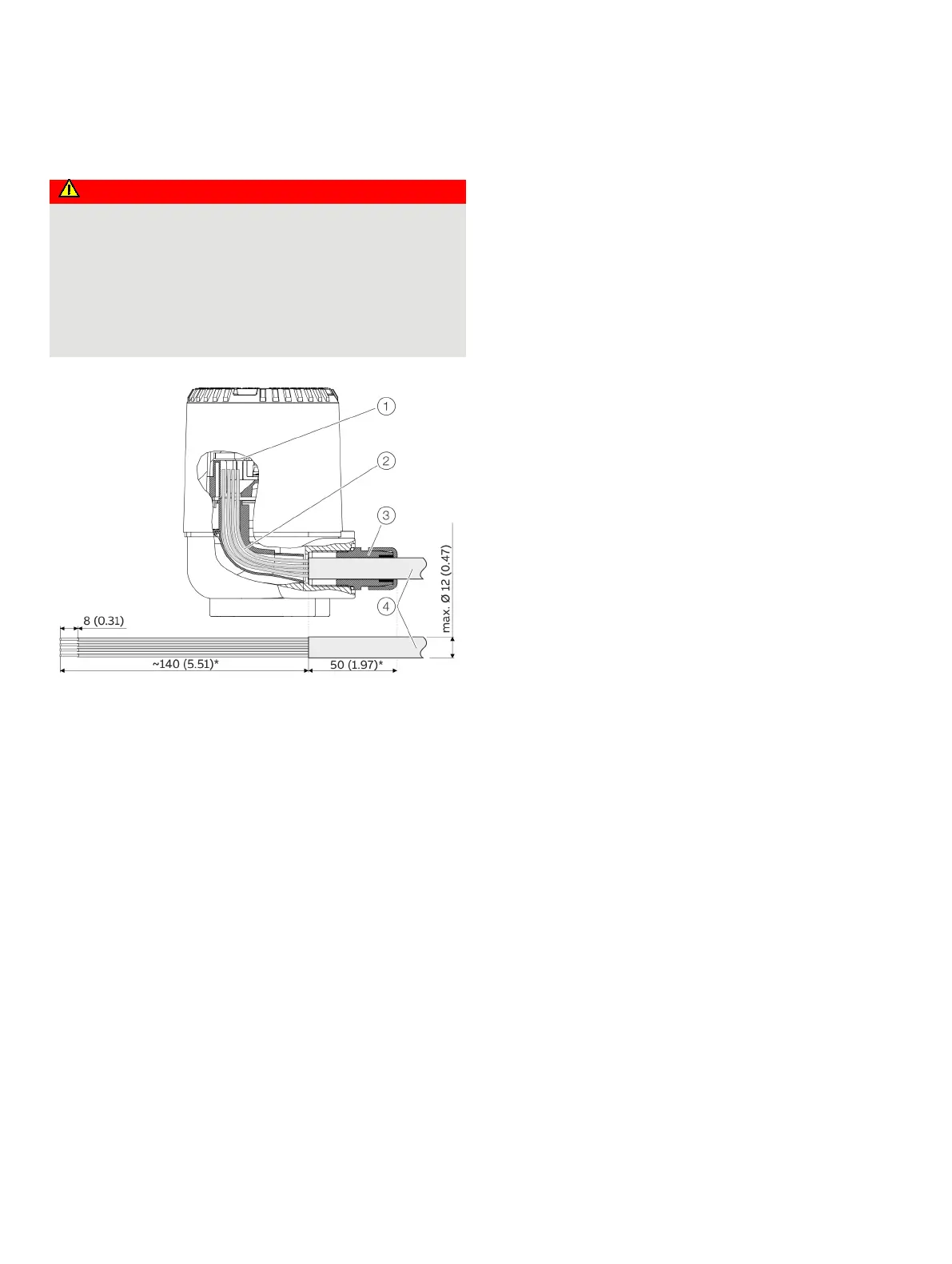
Terminal for sensor connection cable
Danger of explosion if the device is operated with the
transmitter housing or terminal box open!
While using the device in potentially explosive atmospheres
before opening the transmitter housing or the terminal box,
note the following points:
• A valid fire permit must be present.
• Make sure that no flammable or hazardous atmospheres
Terminal compartment
Cable entry
Cable gland
Sensor connection cable
Figure 28: Connection to the transmitter, dimensions in mm (in.)
1. Tighten the lock screw under the housing cover.
2. Unscrew the housing cover.
3. If available, pull out the LCD indicator carefully
4. Strip the sensor connection cable as shown and attach wire
end sleeves.
A line length of 190 mm should be ensured between the cable
gland entry and the terminals. 140 mm should be stripped
from the cable jacket along this length*.
5. Guide the sensor connection cable through the cable glands
and into the housing. Then tighten the cable glands*.
6. Connect the wires as per the connection diagram.
7. If there is one, carefully insert the LCD indicator in the
previous / required position.
8. Screw the housing cover back on.
9. Loosen the lock screw until the housing cover is firmly in
place.
* If an increased electromagnetic interference emission is to be expected at
the installation site, for increasing the interference immunity, we
recommend stripping more than 140 mm (e.g. 143 mm) from the sensor
cable. After inserting the sensor connection cable in the cable gland, pull
back the cable from the stop by the relevant amount, then tighten the cable
gland.