Operation Manual / A100-L
1 Introduction / 1.3 Layout and function of the turbocharger
© Copyright 2021 ABB. All rights reserved. HZTL4034_EN Rev.T December 2021
Mode of operation
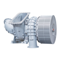
The turbocharger is a turbomachine and consists of the following main components:
¡ Turbine
¡ Compressor
These components are installed on a common shaft and form the rotor.
The exhaust gases of the internal combustion engine flow through the gas inlet casing (08)
and the nozzle ring (07) onto the turbine wheel (06). The turbine wheel uses the energy con-
tained in the exhaust gas to drive the rotor and, hence, the compressor wheel(11).
The exhaust gases then reach the atmosphere through the exhaust gas pipe connected to
the gas outlet casing(05).
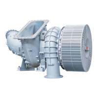
The compressor wheel (11) sucks in fresh air and presses the compressed air into the cylin-
ders.
The air passes through the filter silencer(01) to the compressor wheel(11). The air then
flows through the diffuser(10) and exits the turbocharger through the compressor cas-
ing(12). An air outlet silencer(13) is optionally available. If installed, this will reduce the
amount of noise generated by the components at the outlet side after the compressor cas-
ing.
The rotor runs in two radial plain bearings(03/04) which are located in the bearing cas-
ing(09) between the compressor and turbine. The axial thrust bearing(02) is located at the
compressor end.
The plain bearings are connected to a central lubricating oil duct which is normally supplied
by the lubricating oil circuit of the engine. The oil outlet always lies at the deepest point of
the bearing casing(09).
The turbocharger is equipped with an oil tank which is integrated in the bearing casing (9).
This oil tank supplies the bearings of the rotor with oil until standstill in the event that a mal-
function of the lubrication oil system causes an emergency stop of the engine.
Page 7 / 141