PREPARATIONS, INSTALLATION AND TAKING INTO OPERATION
8
MODEL GRID CONNECTION MODEL VARIANT
3W22A2
230 / 400 V
50 Hz 32 A
Four-wire system with three outer conductors and
neutral conductor; two integrated charging sockets
according to IEC 62196-2 Type 2 for the separately
available Mode 3 charging cable; access control via
RFID;
internal Type A RCCB; internal DC fault current
detection
; max. charging output up to 2x 11 kW
WARNING!
The information and technical specifications contained in this manual re-
late exclusively to the model variants mentioned in these instructions
and must not be transferred to other wallbox models. These variants are
delivered with specific instruction manuals where necessary.
Should your wallbox variant not be described in this manual, please con-
tact ABL technical support: Do not under any circumstances install the
wallbox in this case, as this could lead to damage to the wallbox, to injury
and/or death.
General requirements of the installation site
Your ABL Wallbox is an electrical device and is therefore subject to particular require-
ments for indoor and outdoor installation. In selecting the installation site, you must
consider the following points:
• Consider all local regulations for electrical installations,
fire protection and accident prevention.
• The wallbox must be installed where it is freely acces-
sible to all authorized users.
• A parking spot must also be planned for in front of the
wallbox so that the vehicle can at all times be reached
with the integrated or with an external charging cable.
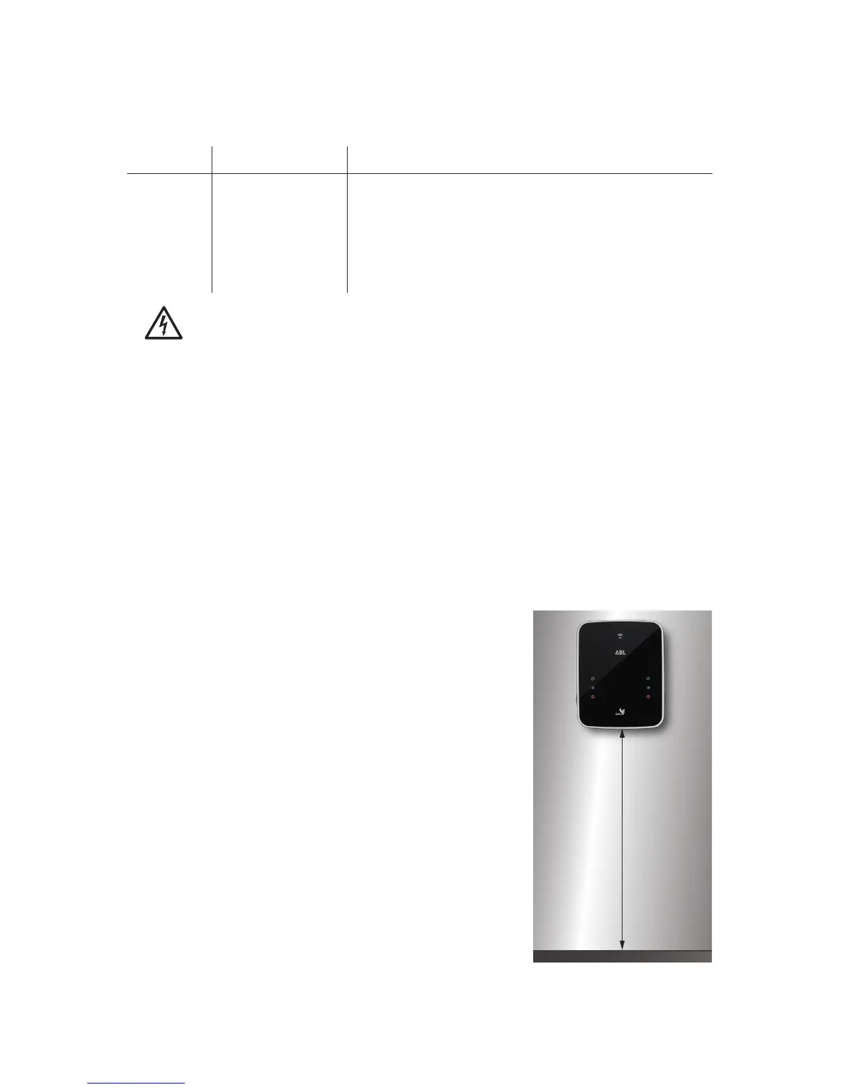
• The recommended installation height is 120 to 140cm
from the floor to the lower edge of the housing. This
recommendation may be adjusted upwards or down-
wards depending on local conditions.
• Sufficient air circulation must be ensured at the installa-
tion site so that the wallbox is cooled during operation:
Always observe the allowed operating temperatures
(see “Technical specifications” on page 16).
• The mounting area must have an even surface that pro-
vides sufficient stability for installing the wallbox.
• The required mounting area for the ABL Wallbox is at least 512 x 429 mm (H x W). All
of the mounting plate of the wallbox must be in contact with the mounting surface.
120 to
140cm
 Loading...