PREPARATIONS, INSTALLATION AND TAKING INTO OPERATION
15
14. Flip the housing cover upwards so
that it clicks into the housing and lock
it with the triangular key supplied.
Taking the wallbox into operation
After mechanical and electrical installation, you must check the correct functioning of
the ABL Wallbox for operation and resolve any malfunctions or installation errors that
may have occurred.
Proceed as follows to take the ABL Wallbox into operation:
1. Switch on the upstream MCB (and RCCB, if present).
2. In addition, switch on the internal RCCB (connection of the wallbox to the electric-
ity grid is established).
When the wallbox is reconnected to the electricity grid, it will initiate the start-up pro-
cedure: This includes an internal test of the electronics to ensure correct functioning.
The internal test routine is indicated by the LEDs on the front of the ABL Wallbox as
follows.
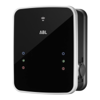
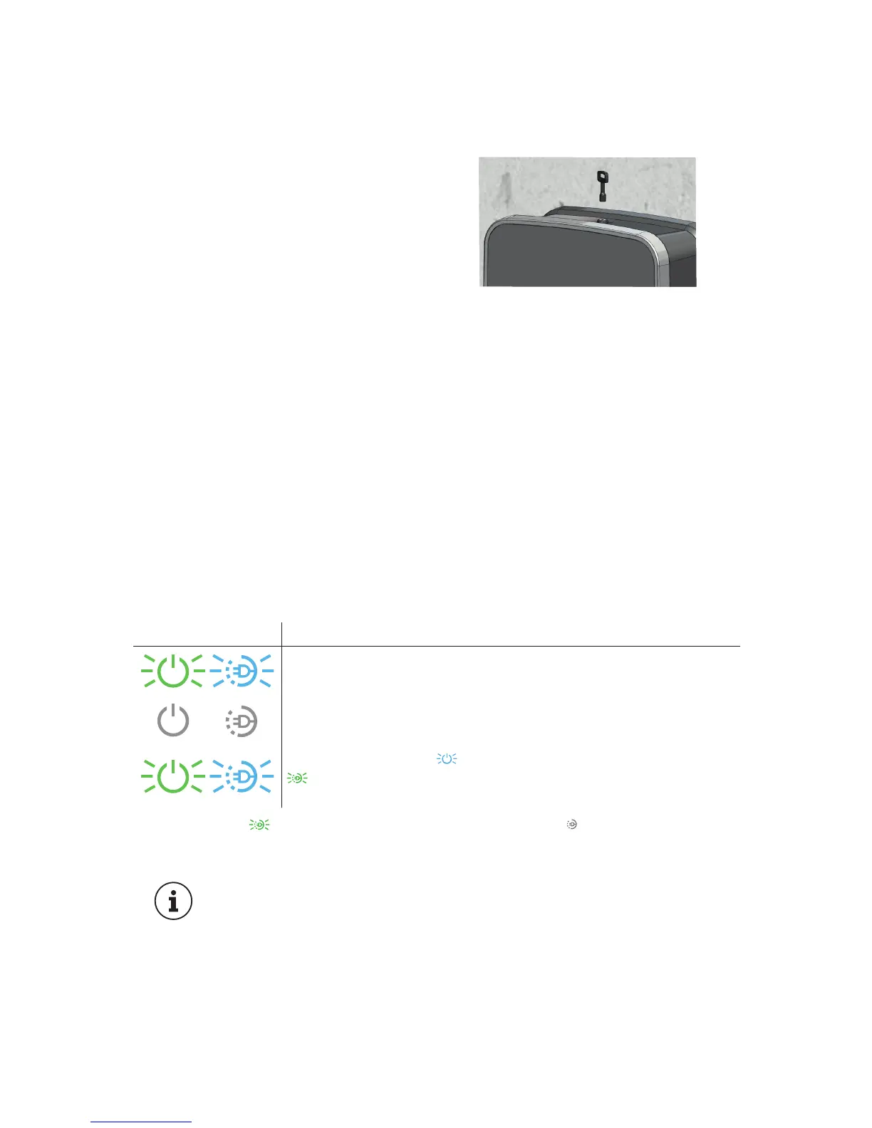
LED DISPLAY DESCRIPTION
Both LEDs flash once …
... and then go out.
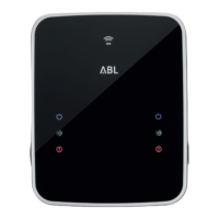
Then, the blue LED (ancillary version) and the green LED
(main version) flash to indicate the current version of the
firmware.
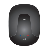
The green LED flashes every 5 seconds, the blue LED goes out. The vehicle
can now be connected for charging. The charging procedure itself is described in the
respective instruction manual.
PLEASE NOTE!
Should a malfunction occur during operation of the ABL Wallbox, this is
shown by the indicator LEDs on the lower part of the housing cover as
an error code. The respective eMH3 instruction manual contains further
information about error states and solutions and taking out of and reiniti-
ating operation of the wallbox.
 Loading...