EasyManua.ls Logo

Ablerex MSII-RT - User Manual

Default Icon
26 pages
Print Icon
To Next Page IconTo Next Page
Loading...
ablerex MSII-RT
Parallel Redundancy On-Line UPS
User’s Manual
6Kva
1
Table of Contents
1. Important Safety Instruction....................................................................2
1.1. An Important Notice................................................................................2
1.2. Storage Instruction .................................................................................4
2. Product Introduction ...............................................................................5
2.1. General Characteristics..........................................................................5
2.2. Symbols on the LCD Display Panel .......................................................7
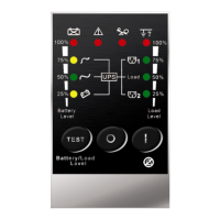
2.3. Panel explanation...................................................................................9
2.4. Communication Port Explanation.........................................................11
3. Installation and Operation.....................................................................12
3.1. Unpacking.............................................................................................12
3.2. Selecting Installation Position...............................................................13
3.3. Installation of Casters Cover ................................................................14
3.4. Terminal Block Explanation..................................................................20
3.5. Operation Test and Installation Instruction...........................................27
4. Troubleshooting Guide.........................................................................38
4.1. Trouble Shooting ..................................................................................38
5. Bundled Software Installation Guide ....................................................40
5.1. Hardware Installation............................................................................40
5.2. Software Installation .............................................................................40
6. Customer Options Slots........................................................................41
6.1. All the below interface cards are with built-in EPO function.................41
6.2. R2E(2nd RS-232 ) card........................................................................41
6.3. RSE(RS-485) card................................................................................41
6.4. USE(USB) card ....................................................................................41
6.5. DCE(Dry Contact) card.........................................................................42
6.6. SNMP Cards.........................................................................................43
6.7. The Installation of those Interface Cards..............................................43
7. Hot Swappable Battery Replacement ..................................................45
8. Specifications .......................................................................................47

Questions and Answers

Summary

1. Important Safety Instruction

1.1. An Important Notice

Key safety instructions for UPS installation and operation, covering electrical safety, environment, and usage.

1.2. Storage Instruction

Guidelines for storing the UPS unit, including recommendations for battery charging during storage.

2. Product Introduction

2.1. General Characteristics

Overview of the UPS's architecture, key features, and operational characteristics.

2.2. Symbols on the LCD Display Panel

Explanation of the various symbols displayed on the UPS's LCD screen for status indication.

2.3. Panel explanation

Detailed explanation of the UPS front panel components, buttons, and indicators.

2.3.2. Rear Panel Explanation

Explanation of the UPS rear panel connections, ports, and connectors.

2.4. Communication Port Explanation

2.4.1. True RS232 type

Details on RS232 interface settings, communication protocol, and pin assignments for UPS connectivity.

3. Installation and Operation

3.1. Unpacking

Instructions for carefully unpacking the UPS module and its associated accessories.

3.2. Selecting Installation Position

Guidance on choosing an optimal installation location for the UPS to ensure performance and longevity.

3.3. Installation

General installation procedures for the UPS unit.

3.3.1. Tower installation

Specific steps for installing the UPS in a tower configuration.

3.3.1.1. Power Module + Battery Module

Installation process for the power module and battery module in tower mode.

3.3.1.2. Power Module+ Isolation Transformer Module+ Battery Module

Installation process for power, isolation transformer, and battery modules in tower mode.

3.3.2. Rack Installation

Specific steps for installing the UPS in a rack-mount configuration.

3.3.2.1. Power Module+ Battery Module

Installation process for the power module and battery module in rack mode.

3.3.2.2. Power Module+ Isolation Transformer Module+ Battery Module

Installation process for power, isolation transformer, and battery modules in rack mode.

3.4. Terminal Block Explanation

Detailed explanation of terminal blocks for UPS output, input, and grounding connections.

3.5. Operation Test and Installation Instruction

Procedures for testing and completing the installation of the UPS unit.

3.5.1. Start Up in Normal Mode

Step-by-step guide for initiating the UPS startup sequence in normal operating mode.

3.5.2. Start-up in Battery Mode (Cold Start)

Instructions for performing a cold start of the UPS using its internal battery power.

3.5.3. Check Measured Values & Figures detected by UPS

How to use the UPS interface to view and interpret detected measurements and figures.

3.5.4. UPS Default Data and Special Function Execution

Overview of UPS default data and how to execute special functions.

3.5.4.2. Press key pad to scroll down the screen and check the UPS settings.

Scrolling through the UPS settings menu to check various configurations.

3.5.4.3. Press scroll up key pad, you may execute special functions.

Executing special functions via the scroll up key, such as buzzer control.

3.5.5. UPS Default Settings and their alternatives

Understanding and configuring default UPS settings and available alternatives.

3.5.5.4. Drawings S1 and S2 mean the bypass input acceptable window...

Configuration of the acceptable input voltage and frequency window for bypass operation.

3.5.5.5. Drawing T means the bypass frequency window of the Inverter Output...

Configuration of the acceptable output frequency window for the inverter.

3.5.5.6. Drawing U means the acceptable Inverter Output Voltage...

Configuration of the acceptable output voltage for the inverter.

3.5.5.7. Drawing V1, V2, V3 and V4 mean the operation modes of the UPS...

Selection and configuration of UPS operation modes like Normal, ECO, or CVCF.

3.5.5.8. Drawing W means the adjustments of the Inverter Output...

Adjustment of the inverter output voltage percentage.

3.5.5.9. Drawing X means a specified address & position of the UPS when the UPS is in Parallel mode.

Setting the address and position for UPS units in a parallel system.

3.5.5.10. Drawing Y means the total numbers of the UPS in parallel.

Configuration of the total number of UPS units in a parallel setup.

3.5.5.11. When all the setting changes are done, you have to press enter key Pad to save...

Procedures for saving or canceling configuration changes made to the UPS settings.

3.5.6. UPS Is Off Due to Unknown Reason and Its Trouble Shooting

Troubleshooting guide for UPS units that have shut off unexpectedly.

3.5.6.2. To release the UPS lock, please check those error messages shown in Chapter 2.2 to trouble shoot...

Steps to release a UPS lock and troubleshoot abnormal conditions using error messages.

3.5.7. Shut Off

Procedures for safely shutting down the UPS unit.

3.5.8. Maintenance Bypass Mode

Instructions and procedures for operating the UPS in maintenance bypass mode.

3.5.8.1.2. Release the cover of the CAM Switch...

Instructions for operating the maintenance bypass switch after releasing its cover.

3.5.8.1.4. To repeat 0, you may put the UPS back to normal working mode...

Steps to return the UPS to normal operation from bypass mode.

4. Troubleshooting Guide

4.1. Trouble Shooting

Comprehensive guide for troubleshooting common UPS malfunctions and issues.

5. Bundled Software Installation Guide

5.1. Hardware Installation

Instructions for physically connecting the UPS communication cable to the computer.

5.2. Software Installation

Guidance on the procedure for installing the UPS monitoring software.

6. Customer Options Slots

6.1. All the below interface cards are with built-in EPO function.

Information on the Emergency Power Off (EPO) function integrated into the interface cards.

6.2. R2 E(2 nd RS-232) card

Details about the R2E (2nd RS-232) interface card, including its function.

6.3. RSE(RS-485) card

Details about the RSE (RS-485) interface card, including its function.

6.4. USE(USB) card

Details about the USE (USB) interface card, including its function and pin assignments.

6.5. DCE(Dry Contact) card

Details about the DCE (Dry Contact) interface card, including its pin assignments.

6.6. SNMP Cards

Information regarding SNMP/WEB and Net Agent II internal cards.

6.7. The Installation of those Interface Cards

General instructions for installing various interface cards into the UPS slots.

7. Hot Swappable Battery Replacement

8. Specifications

Ablerex MSII-RT Specifications

General IconGeneral
ModelMSII-RT
LCD DisplayYes
Operating Temperature0-40 °C
Battery TypeSealed Lead Acid
Communication PortsUSB, RS232
Form FactorTower
Efficiency>90%
Humidity20-90% non-condensing

Related product manuals