Do you have a question about the Ablerex 3 MS series and is the answer not in the manual?
Details VR calibration and switch setting, including procedures for different CPU versions.
Troubleshoots UPS behavior when utility power is lost but it operates on battery.
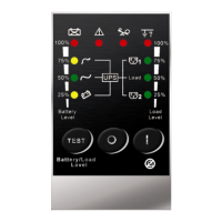
Guides on diagnosing issues indicated by fault LEDs and lack of output power.
Addresses the problem of a burnt input fuse and its potential causes.
Outlines troubleshooting for UPS failures during power outages or blackouts.
Guides on resolving scenarios where the UPS shows no indicators and produces no output.
Troubleshoots the issue where the fan remains active after the UPS is switched off.
Offers a flowchart for rapid identification and resolution of common UPS malfunctions.
Troubleshoots UPS behavior when utility power is lost but it operates on battery.
Guides on diagnosing issues indicated by fault LEDs and lack of output power.
| Model | 3 MS series |
|---|---|
| Category | UPS |
| Topology | Line Interactive |
| Operating Temperature | 0-40°C |
| Storage Temperature | -15-45°C |
| Input Voltage | 230VAC |
| Output Voltage | 230VAC |
| Frequency | 50/60 Hz |
| Battery Type | Sealed Lead Acid Maintenance-Free |
| Battery Backup Time | Varies with load (typically 5-45 minutes depending on model and load) |
| Communication Interface | USB |
| Humidity | 0-95% (non-condensing) |
| Dimensions (W x D x H) | Varies by model |
| Weight | Varies by model |