4
1.2 . System Layout and Description
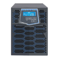
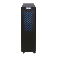
1.2.1. Front Panel and Rear Panel Layout
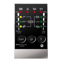
1.2.1.1. Front Panel Explanation
1.
Main Switch
This is control the on/off of the UPS
2.
Self Test OK LED
Green LED lights up if self test is O.K.
3.
Test/Silence
a. To silence alarm by pressing the button.
b.1.For Standard Unit
To execute the self test of the UPS by pressing
the button over 10 sec.
b.2.For Unit with Manual Bypass function
(Special order required)
To press the button over 5 seconds, the UPS will
be switched to Bypass mode and vice versa.
c. To illustrate the percentage of output load level at
AC Mode, and the battery energy level at Backup
Mode by pressing the button.
4.
Fault LED
Red LED lights up if UPS is faulty.
5.
Inverter LED
a. Inverter On: Green LED light up
b. 75% for load & battery level.
6.
Utility LED
a. AC normal: Green LED lights up.
b. 100% for load & battery level
7.
Bypass LED
Amber LED lights up when UPS is in Bypass mode.
8.
Battery low LED
a. Battery low :Red LED lights up
b. 50% for load & battery level
9.
Over load LED
a. Over load condition: Red LED lights up
b. 25% for load & battery level.
10.
Load Level LED’s
Push the Test/Silence button for few seconds when Utility
is normal, the LED’
Battery Level LED’s
Push the Test/Silence button for few seconds when Utility
Is abnormal, the LED’s combined by Utility, Inverter,
Battery Low and Overload LED’s will show you the
percentage of the battery energy left.
 Loading...