18
NOTE: The function of terminals TB-13A, TB-13B, TB-13C, TB-14, TB-15, TB-30, and TB-31 are
dependent on the programming of certain parameters. Refer to Section 15.0 - DESCRIPTION OF
PARAMETERS.
Additional information on operating the drive from the terminal strip can be found in Section 10.0.
The following diagrams provide a quick reference to wire the drive for the most common configurations.
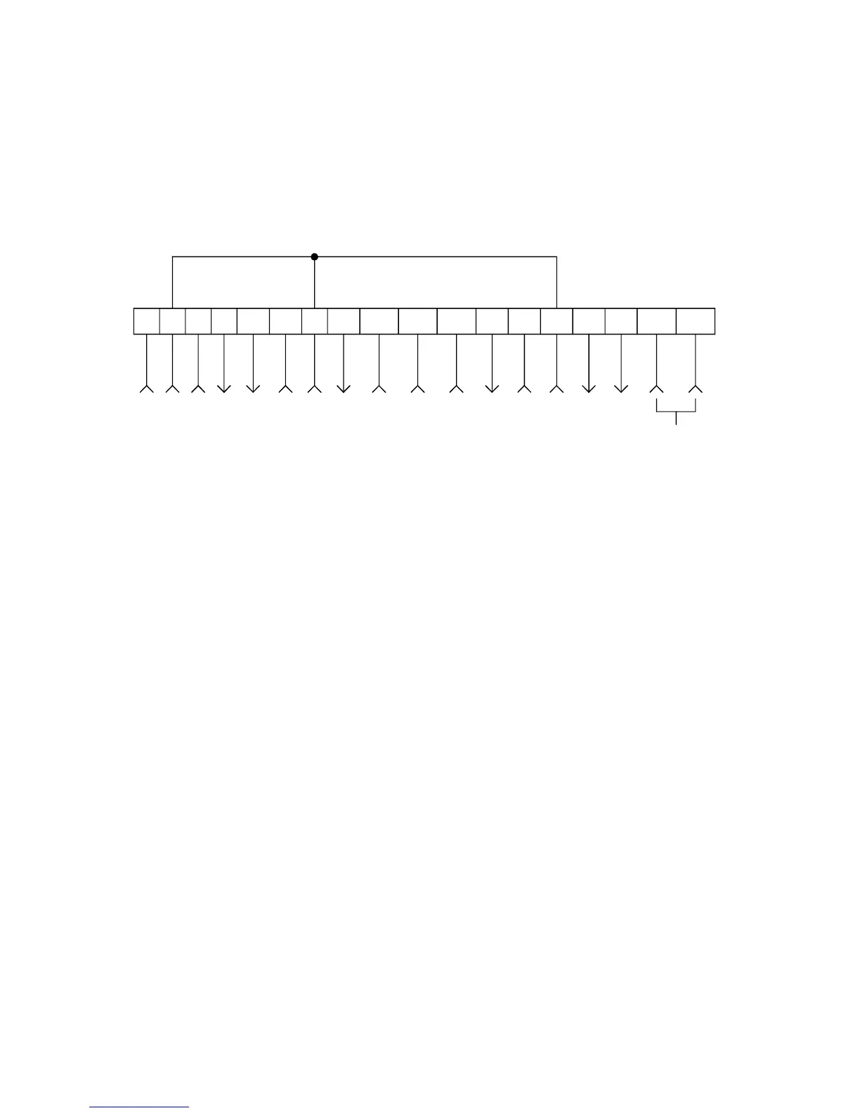
11.0 SCF CONTROL WIRING DIAGRAMS
11.1 SCF TERMINAL STRIP
Shown below is the terminal strip on the main control board, along with a brief description of the
function of each terminal.
12
56
12
TXA TXB
2 13A 13B 13C14 15 2
STOP
CIRCUIT COMMON
0-10 VDC SPEED REFERENCE INPUT
10 VDC SUPPLY FOR SPEED POT
0-10 OR 2-10 VDC OUTPUT: FREQ. OR LOAD
0-10 OR 2-10 VDC OUTPUT: LOAD
CIRCUIT COMMON
START
TB-13A FUNCTION SELECT
TB-13B FUNCTION SELECT
TB-13C FUNCTION SELECT
OPEN-COLLECTOR OUTPUT
OPEN-COLLECTOR OUTPUT
RS-485 SERIAL
COMMUNICATIONS
CIRCUIT COMMON
4-20 mA SPEED REFERENCE INPUT
11 25 31
30
12 VDC SUPPLY (50 mA MAX)
The TB-2 terminals are internally connected to each other