46
P58 KEYPAD AND PROTECTION STATUS
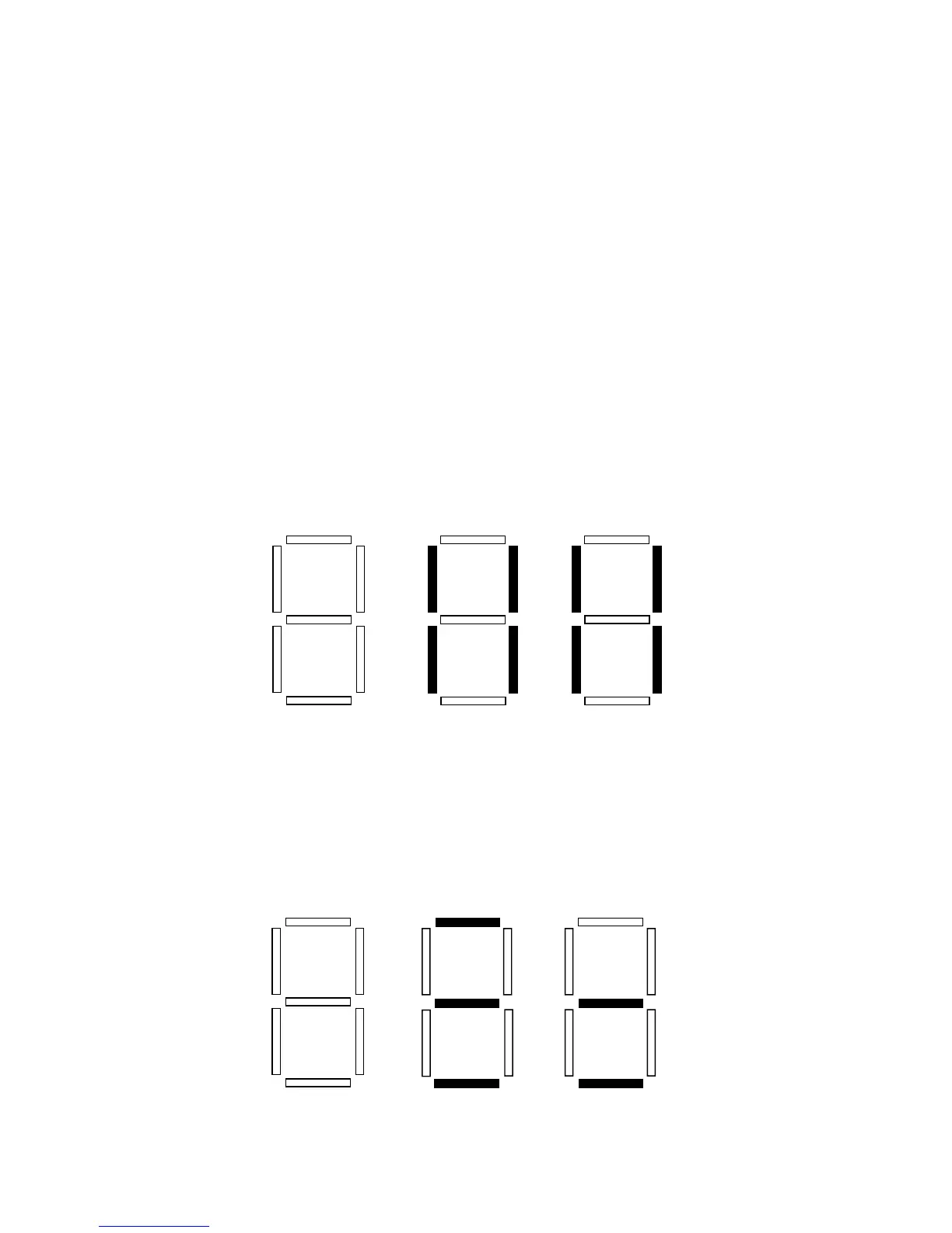
This indicates the status of the buttons on the keypad, and the status of the protective circuitry in the
drive, using the horizontal segments of the LED. An illuminated segment indicates that the
corresponding button is pressed, or the protective circuit is active. See the diagram below:
P54 MOTOR LOAD
This displays the motor load in percent of the drive’s output current rating.
P55 0-10 VDC ANALOG INPUT
This displays the level of the 0-10 VDC analog input signal at TB-5. A reading of 100% indicates a
10 VDC input at TB-5.
P56 4-20 mA ANALOG INPUT
This displays the level of the 4-20 mA analog input signal at TB-25. A reading of 20% indicates a 4
mA input at TB-25, and a reading of 100% indicates a 20 mA input at TB-25.
P57 TERMINAL STRIP STATUS
This indicates the status of several terminals using the vertical segments of the LED display. An
illuminated segment indicates that the particular terminal is closed with respect to TB-2. The CHARGE
RELAY is not a terminal, and should always be illuminated. See the diagram below:
CHARGE
RELAY
TB-1
TB-12
TB-13A
TB-13B
TB-15
TB-14
TB-13C
FCLIM
Mode
OUTPUT
FAULT
!
"
NOTE: FCLIM is an abbreviation for Fast Current Limit.