Wiring Harness Installation Considerations
• The plugs that connect to the ECU will only t in the desired orientation. Do
not force the connectors into the wrong mating connector.
• Make sure to press all connectors on rmly until an audible “click” sound can
be heard from the lock.
• Route all wiring away from exhaust or other hi-temp areas.
• Use Rubber Grommets for areas where sharp metal could eventually wear
through the wire insulation.
Step-By-Step
•ECU Main Harness
1.) First connect the Main Harness at the ECU then route each section to each
component on the vehicle.
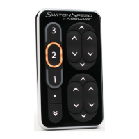
2.) Route the SwitchSpeed™ harness (Mini USB Cable) to the inside of the
vehicle and leave until later in installation. Route the single purple wire labeled
“HEADLIGHTS” to a 12V source in the vehicle Headlight Switch. Check the
manufacturer’s specs for a 12V Headlight source inside the vehicle (You can also
use a 12V wire from the closest marker light instead of running it to the Head-
light Switch inside the vehicle.). This will allow the SwitchSpeed™ Controller’s
backlighting to dim automatically when the headlights are on.
3.) Route the single orange wire labeled “IGN_12V” to an ignition source.
4.) Route the 3-wire Tank Pressure Sensor sub harness (green, red, and black
wires) labeled “P_SENS” to the sensor.
5.) Route the single yellow wire labeled “COMP_1” with a 3 Amp fuse to trigger
the Compressor Relay(s).
6.) Route the single red wire labeled “BATT_12V” with a 10 Amp fuse to the
vehicle battery.
7.) Mount the single black wire labeled “EC_GND” with the VU4 ground.
Install Wiring Harnesses:
See System Diagram
on pages 4-5.
CLICK !