SP8026-1909
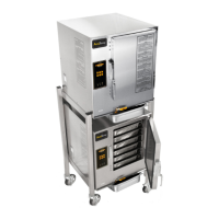
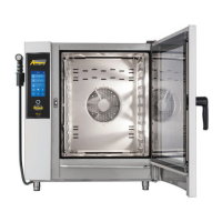
EVOLUTION ELECTRIC STEAMER
7
1.0 Sequence of Operation
1.1 WATER LEVEL SYSTEM &
INDICATOR LIGHTS:
PWR Button Pushed & Water Level Is
Below the Low Water Level Sensor -
AUTO-FILL
• The Low Water Light Indicator will
be lit.
• PRE is displayed on the Control/
Keypad Board.
• The Water Sensor Board sends a
signal to the Water Sensor Board’s
K1 Relay to open the Auto-Fill Valve
and start filling the steam chamber
with water.
• The red LED light on the Water
Sensor Board will be flashing
continuously.
PWR Button Pushed & Water Level Is
Below the Low Water Level Sensor -
MANUAL FILL
• The Low Water Light Indicator will
be ON and Alarm will sound.
• PRE is displayed on the Control/
Keypad Board.
• The red LED light on the Water
Sensor Board will be flashing
continuously.
PWR Button Pushed & Low Water
Level Sensor Is Satisfied - MANUAL &
AUTO-FILL
• The Low Water Light Indicator and
Alarm (only manual fill units use an
alarm for low water condition), will
be OFF.
• This is the minimum water level
needed for the contactor to close and
turn the Cast Heater ON.
• The red LED light on the Water Sensor
Board will have about a 1 second flash
delay.
Water Level Is At the High Limit Water
Level Sensor - AUTO-FILL
• When the water level in the chamber
touches the High Water Limit Probe,
the Water Sensor Board will continue
to activate the Auto-Fill Valve for an
additional 30 seconds; and then turns
the valve o. (This will occur every
time the water level falls below the
High Limit Probe).
• The red LED light on the Water Sensor
Board will have about a 2 second flash
delay.