SP8026-1909
EVOLUTION ELECTRIC STEAMER
47
4.6 Removal and Replacement of Temperature Sensors
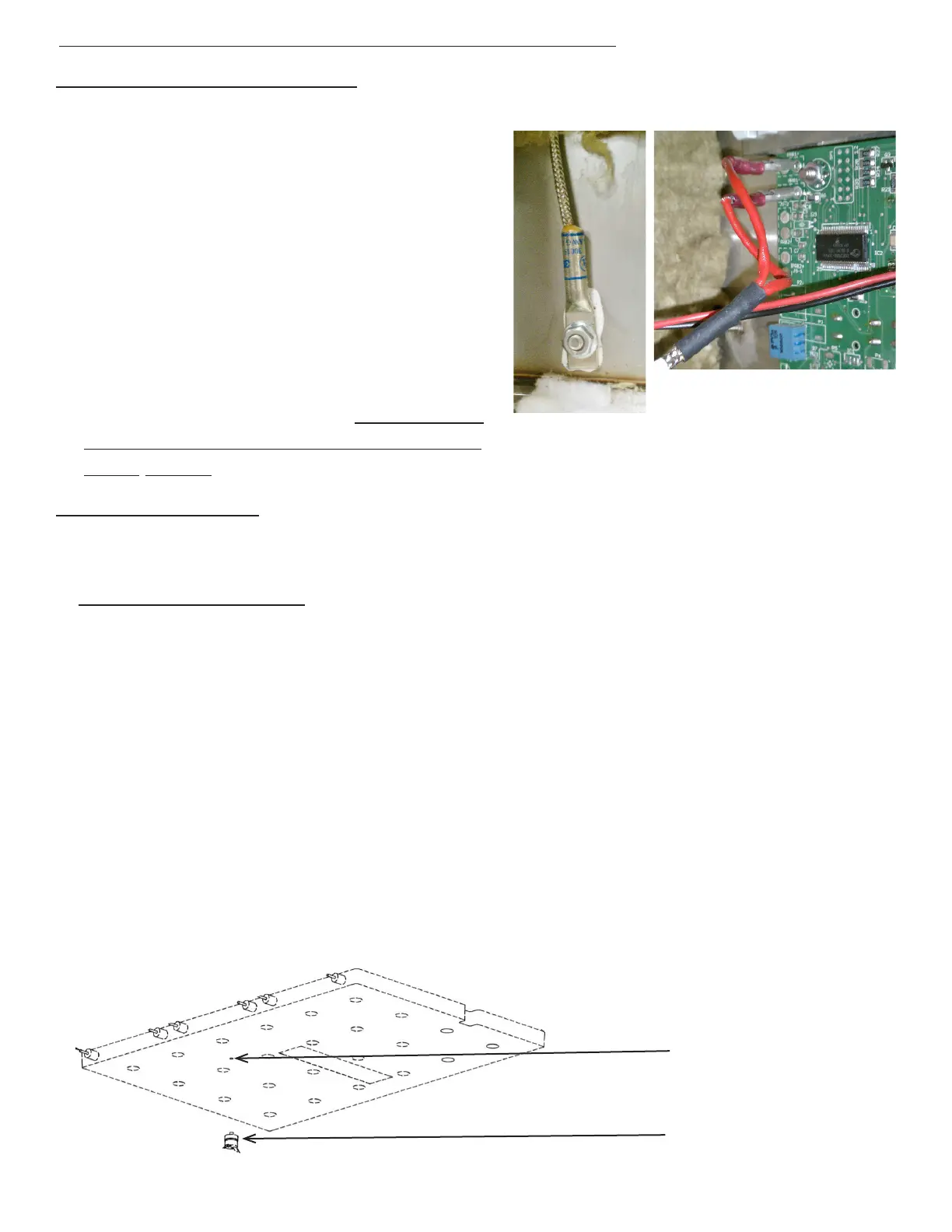
TEMPERATURE (RTD) SENSOR
1. Unplug the Unit.
2. Remove the Left-Side, Right-Side, and
Top Panel by removing the Sheet Metal
Screws holding it in place.
3. Disconnect the probe wires from the
Control/Keypad Panel and pull them
from the left, over the top, to the steam-
er’s right-side (the wires to the location
pins are enter-changeable).
4. Remove the mounting nut and then re-
move the Temperature (RTD) Sensor.
5. Re-install in reverse order. Ensure Ther-
mal Paste is applied to the Temperature
(RTD) Sensor.
FIG 4.6A
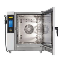
OVERTEMP SWITCH
1. Unplug the unit and drain all the water out of the steamer.
2. Remove Left-Side panel by removing the Sheet Metal Screws holding it in place.
3. Using an additional person, turn the unit upside-down and remove its legs. (Unbolt unit from
stand and then turn unit upside-down if applicable.)
4. Remove the Bottom Cover by removing the Sheet Metal Screws holding it in place. (Remove
Drain Pan Rails if applicable.)
5. Remove insulation as needed to access the Cast Heater. (Note the insulation’s location to
ensure proper fitting when re-installed.)
6. Disconnect the wires to the Overtemp Switch (note the wire color to its location pin).
7. Unscrew the Overtemp Switch, and remove it from the bottom of the Cast Heater. Apply heat
transfer compound to the bottom and stud on the high-limit thermostat and screw it in the
threaded hole on the rough side of the heater. It should be tight, but only finger tight. Do not
use any tools to tighten it.
8. Replace the insulation covering the heater
9. Connect the wires to the high-limit thermostat. Push the wires into the slit in the insulation so
they don’t rub on the bottom cover. Push the thermostat connectors down so they don’t rub
either.
10. Reassemble the steamer and test the unit operation
Overtemp Switch
Overtemp Switch
tap in Cast Heater