3-24 Machine Maintenance Procedures
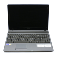
7. Lift upper cover to remove (Figure 3-25).
Figure 3-25. Upper Cover
Upper Cover Installation 0
1. Align upper cover to lower cover.
2. Press along edges to secure all latches.
3. Install and secure seven (7) screws (J) to upper cover (Figure 3-23).
4. Connect the following cables (Figure 3-23):
power board FFC cable (C) to mainboard connector (D)
touchpad FFC cable (E) to mainboard connector (F)
left speaker cable (G) to mainboard connector (H) and right speaker cable (L) to
mainboard connector (M).
5. Place computer on surface, face down.
6. Install and secure the following screws: (Figure 3-22)
ten (10) screws (A) to lower cover
four (4) screws (B) to battery bay.
7. Install keyboard, HDD module, DIMM module, WLAN module and ODD module.
ID Size Quantity Screw Type
A M2.45x8 10
B M2x3+3.5 4
J M2.5x5 7

 Loading...