ALWAYS A STEP AHEAD 5
EN
3.1 Cable and device connection
Start off by connecting the potential equalization cable (greenish-yellow marking) to ensure a
sufficient potential equalization.
The type plate on the side of the housing indicates the power grids the unit is rated for.
Carefully connect all the needed cable connectors to the unit. To prevent the risk of electrical
shock, this unit may only be connected to a supply system with a protective earth. Check that all
cables are properly connected. Attaching strain reliefs to the unit is not necessary for the custo-
mer.
For complete disconnection from the mains, turn off the mains switch or pull the power plug from
the outlet. Never pull on the cable and always hold onto the plug of the cable when disconnecting
the power system connections. Do not set up the unit under conditions that impede the discon-
nection from the mains.
When creating an electrical connection with other devices or when operating the unit at a portable
multiple socket outlet, ensure compliance to IEC 60601-1 in the currently valid version. Connec-
tions without any direct electrical contact may help to avoid extensive conformity re-evaluations
for that newly created electrical system and to maintain the conformity assessments of the
individual devices instead. As an example, galvanic isolators can be integrated to many models
optionally.
Furthermore, a functional system is created by exchanging data with other devices. This applies in
particular if this functional system has a medical purpose, e.g. when the unit becomes part of an
endoscopy system. The validity of any assured properties and conformity to standards for the unit
would not extend to the new functional system. Instead, the party which is placing this newly crea-
ted system on the market is responsible for its conformity to applicable regulations and standards.
There might be unforeseeable interactions or even malfunctions on one or both units if the unit is
connected to other devices.
We would be glad to provide technical support and resolve unanswered questions.
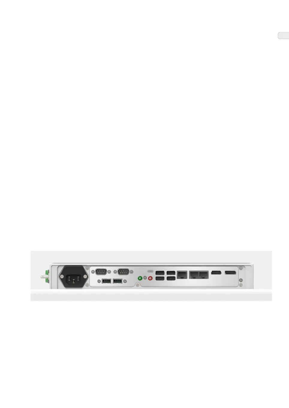
Figure: Example of a connector interface on the lower side of your OR-PC
®
Available connectors will vary depending on the configuration you have chosen for your unit.