AR-B1479 User’s Guide
17
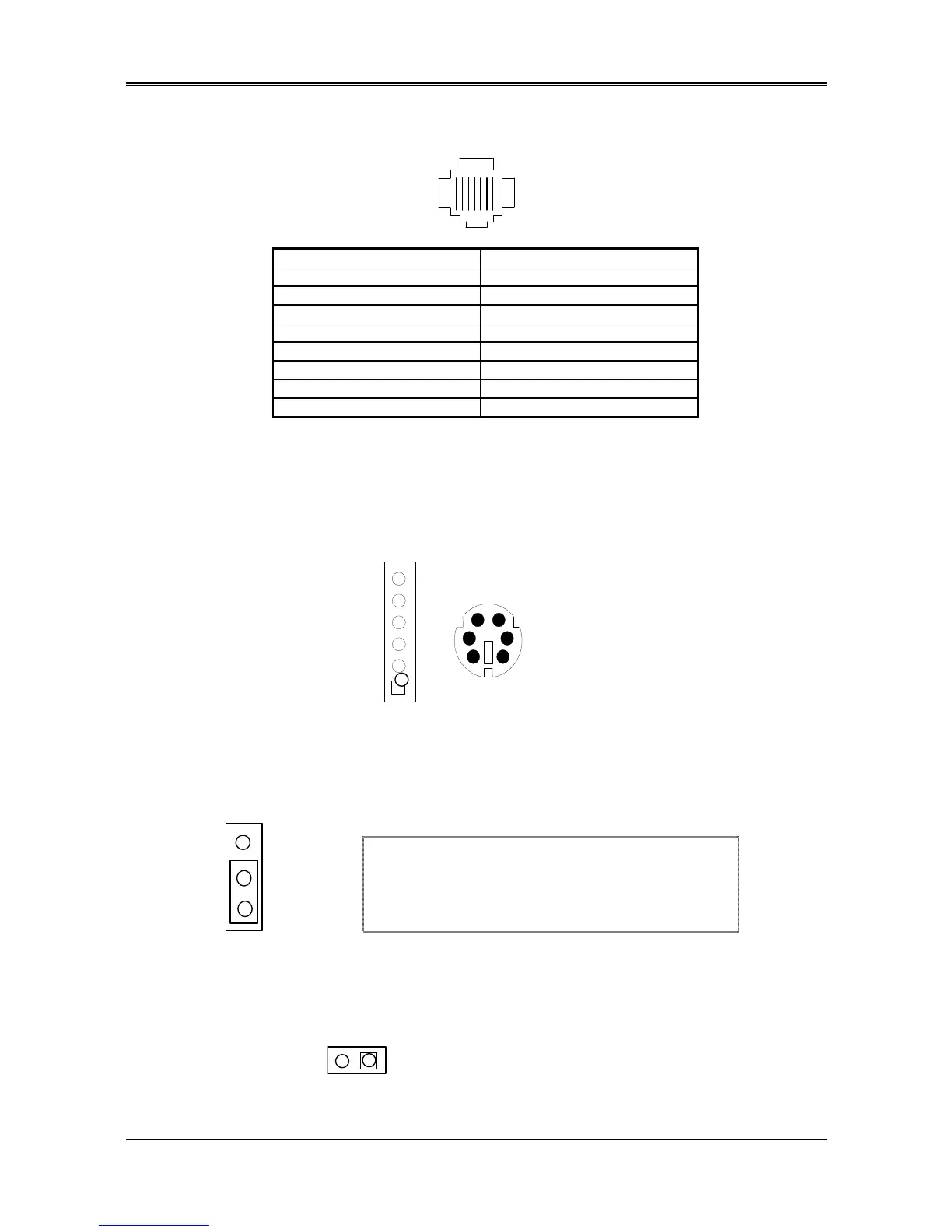
3.2.3 Ethernet RJ-45 Connector (LAN1)
The LAN1 RJ-45&LED headers are the standard network headers. The following table is the pin assignment.
18
PIN (LAN1) FUNCTION
1 TPTX+
2 TPTX -
3 TPRX+
4 Not Used
5 Not Used
6 TPRX -
7 Not Used
8 Not Used
RJ-45 Pin Assignment
3.2.4 PS/2 Mouse Connector (CN2 & PS1)
To use the PS/2 interface, an adapter cable has to be connected to the CN2 (6-pin header type) connector. This
adapter cable is mounted on a bracket and is included in your AR-B1479 package. The connector for the PS/2
KB/mouse is a Mini-DIN 6-pin connector. Pin assignments for the PS/2 port connector are as follows:
KBCLK
Figure 0-2 CN2 & PS1: PS/2 Mouse Connector
3.2.5 PS-ON Header (CN1)
1. PS-ON
2.VCC
3.5VSB
CN1
3.2.6 Reset Header (J1)
The J1 is a reset switch. Shorting these two pins will reset the system.
2
n When AT power supplier is applied, jumper 2&3 should
be tied together. (Factory preset)
n When ATX power supplier is applied, pin1&pin 3 should
be connect to proper location of ATX power supplier.