AR-B1479 User’s Guide
23
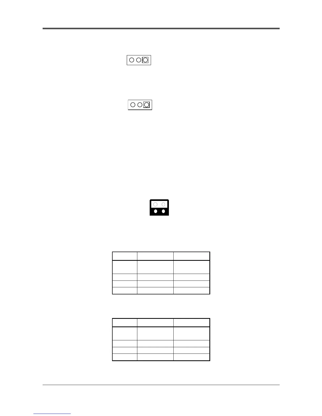
(3) RS-485 Header (J9)
3
1. N485+
2. N485-
3. GND
J9
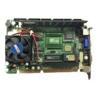
3.2.18 Touch Screen Connector (J6 & J7)
3
1. RXDF
2. TXDF
3. CGND
Figure 0-8 J6&J7: Touch Screen Connector
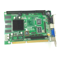
3.2.19 D.O.C. Memory Bank Address Select (JP3)
This section provides the information about how to use the D.O.C. (Disk On Chip). It divided into two parts:
hardware setting and software configuration.
Step 1:
Use JP3 to select the correct D.O.C. memory bank address.
Step 2:
Insert programmed Disk On Chip into sockets U12 setting as DOC.
Step 3:
Line up and insert the AR-B1479A and AR-B1479B card into slot of your computer.
Factory Preset
Figure 0-9 JP3: D.O.C. Memory Address Select
(Only for 1479A)
Table 0-4 D.O.C. Memory Address
(Only for 1479B)
JP3 Address Note
1-2
3-4
D200:0000
3-4 CC00:0000
1-2 C800:0000 Factory Preset
X D000:0000
JP3 Address Note
1-2
3-4
D000:0000
3-4 D200:0000
1-2 D400:0000 Factory Preset