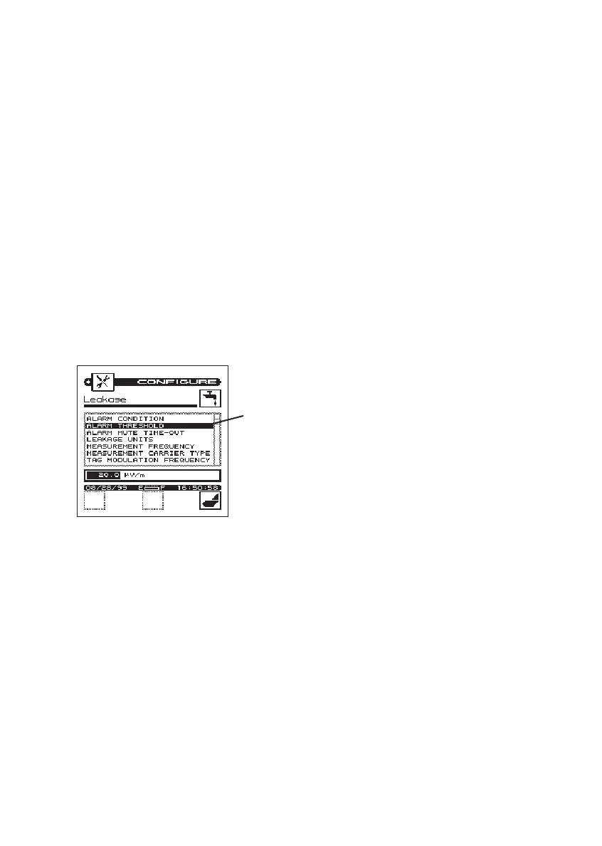
• Alarm Condition
• Alarm Threshold
• Alarm Mute Time-Out
• Leakage Units
• Measurement Frequency
• Measurement Carrier Type
• Tag Modulation Frequency
• Reference Distance
• Peak-hold Reset Period (i.e. Peak-
the-Leak)
• Edit Antenna Type (i.e. Antenna
Factor)
While in the Configure Screen, you
can set-up of all the functions listed
above using the following procedures.
d.Use arrow up or down key to
select the function (above) you
want to change.
e. Press the “ENTER” key.
f. For each function, review the
options provided at the bottom of
the screen by pressing the up or
down arrow key.
g. Select an option, then lock your
choice into the meter’s memory
by pressing the “ENTER” key.
h.In some situations, specific num-
bers can be entered manually
from the keypad. Review the
instructions provided for setting-
up each function.
i. Repeat above steps (d through h)
to set-up each function.
Alarm Condition: This setting deter-
mines when the alarm is triggered.
When setting the alarm condition, the
field technician should select “thresh-
old” or “threshold and tag”. For exam-
ple, if the field technician is using a
tag, the “threshold and tag” should
be selected.
Set function by choosing one of the
following choices. Press “ENTER”
when complete.
a. Threshold and tag
b.Tag
c. Threshold
d.Disabled
Note: If the audio alarm becomes
annoying when doing leakage meas-
urements, it is possible to mute the
alarm for a few seconds by pressing
the “ENTER” key.
Alarm Threshold: This is the leakage
measurement level at which the alarm
will occur and must be set according
to uses leakage requirements. To com-
ply with FCC rules the CLI instrument
threshold should be set at 20 µV/m.
3-9
select function