Hardware Manual
29
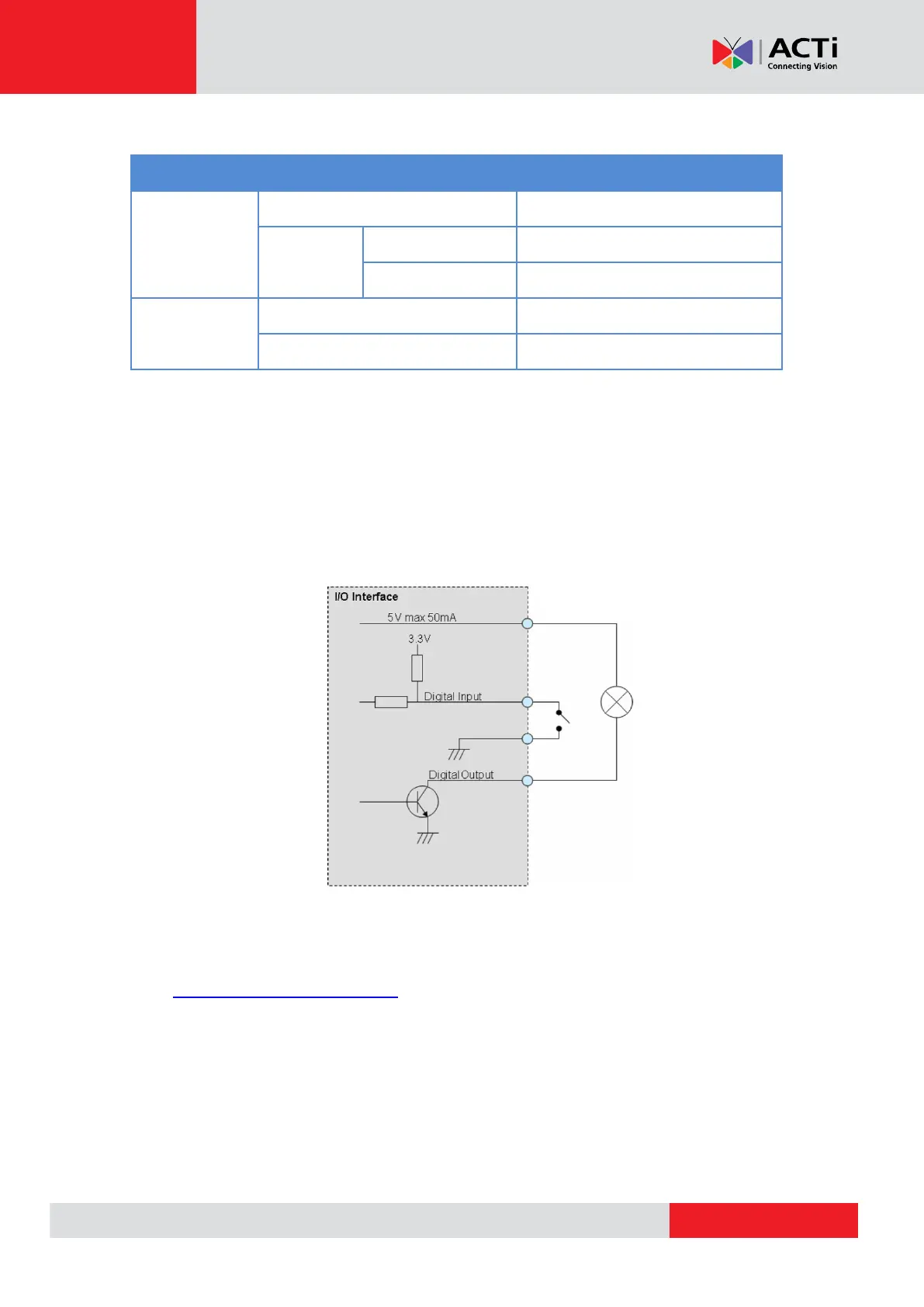
The table below shows the DI/DO connection specifications:
TTL - compatible logic levels
Transistor (Open Collector)
Typical Connection
Based on these specifications, if the DI device has a voltage of 3.3V or the DO device has a
voltage of 5V (< 50mA), then the camera can supply internal power to these devices and there is
no need to connect the DI/DO device to an external power source.
In this case, wire connection to Pins 1 to 4. Use the GND and DI pins to connect a DI device and
use the 5V and DO pins to connect a DO device. See wiring scheme below:
NOTE: For more information on DI/DO connections, please refer to the Knowledge Base
article All about Digital Input and Digital Output downloadable from the link below
(http://Download.acti.com?id=516).