Hardware Manual
25
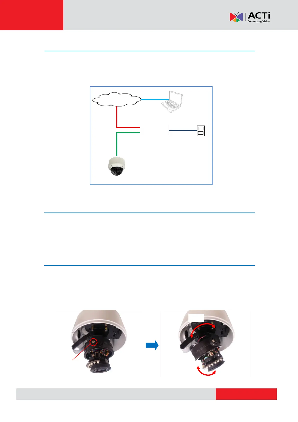
Step 4: Connect to Network
Connect the other end of the network cable to a switch or injector. Then, connect the switch or
injector to a network or PC and a power source. See Power-over-Ethernet (PoE) example
connection diagram below.
PoE Injector /
PoE Switch
Ethernet Cable
(Data + Power)
Step 5: Access the Camera Live View
See Accessing the Camera on page 35 for more information on how to access the Live View of
the camera.
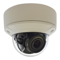
Step 6: Adjust the Viewing Angle
Based on the live view, adjust the viewing angle and orientation of the camera.
1. Turn the lens module to pan the camera.
2. Loosen the two (2) tilt adjustment screws and then tilt the camera to desired angle.
3. Tighten the tilt adjustment screws to fix the lens position.