EN • 18
ENGLISHFRANCAISNEDERLANDSESpAñoLITALIANoDEuTSCH
664Y0200.C
• Measure the speed of the impeller that is mounted on the motor
shaft. Adjust the speed of the fan according to the parameters
(Start, Min., Max.) listed in the table of setting parameters on
Page 17 by turning the potentiometer screw (counter-clockwise
to reduce the fan speed and clockwise to increase it).
Fan speed for burner BG 2000-MV :
If the fan of a BG 2000-MV burner is replaced, the fan's speed
is controlled directly by the PWM connector which connects the
fan to the p.c.b.
The potentiometers on the p.c.b. (Start, Min. and
Max.) must be adjusted by an engineer approved by
ACV.
A
fig. 15
1
2
3
4
fig. 16
BuRNER CHARACTERISTICS
BURNER DISMANTLING PROCEDURE
Forsafetyreasonsitisessentialthatyouisolatethe
powersupplyandthegassupplyvalvebeforecarrying
outanyworkontheburner.
Dismantlingtheburner
1. Remove the burner cover.
2. Disconnect the gas connector and the electrical plugs of the
burner.
3. Disconnect the air supply pipe from the venturi.
4. Take off the burner chamber plate by undoing the two
retaining nuts.
Burnerre-assembly
The burner is re-assembled in the reverse order of dismantling
(Step 4 to Step 1).
SETTING PROCEDURE IN THE EVENT OF FAN
REPLACEMENT
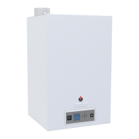
Fan speed for burner BG 2000-SV : (fig. 15)
• Remove the green plug on the front of the fan to gain access
to the adjuster screw on the potentiometer (A).
PROCEDURE FOR ADJUSTING OR REPLACING
THE % OF CO
2
• Measure the burner combustion with an electronic flue gas
analyser.
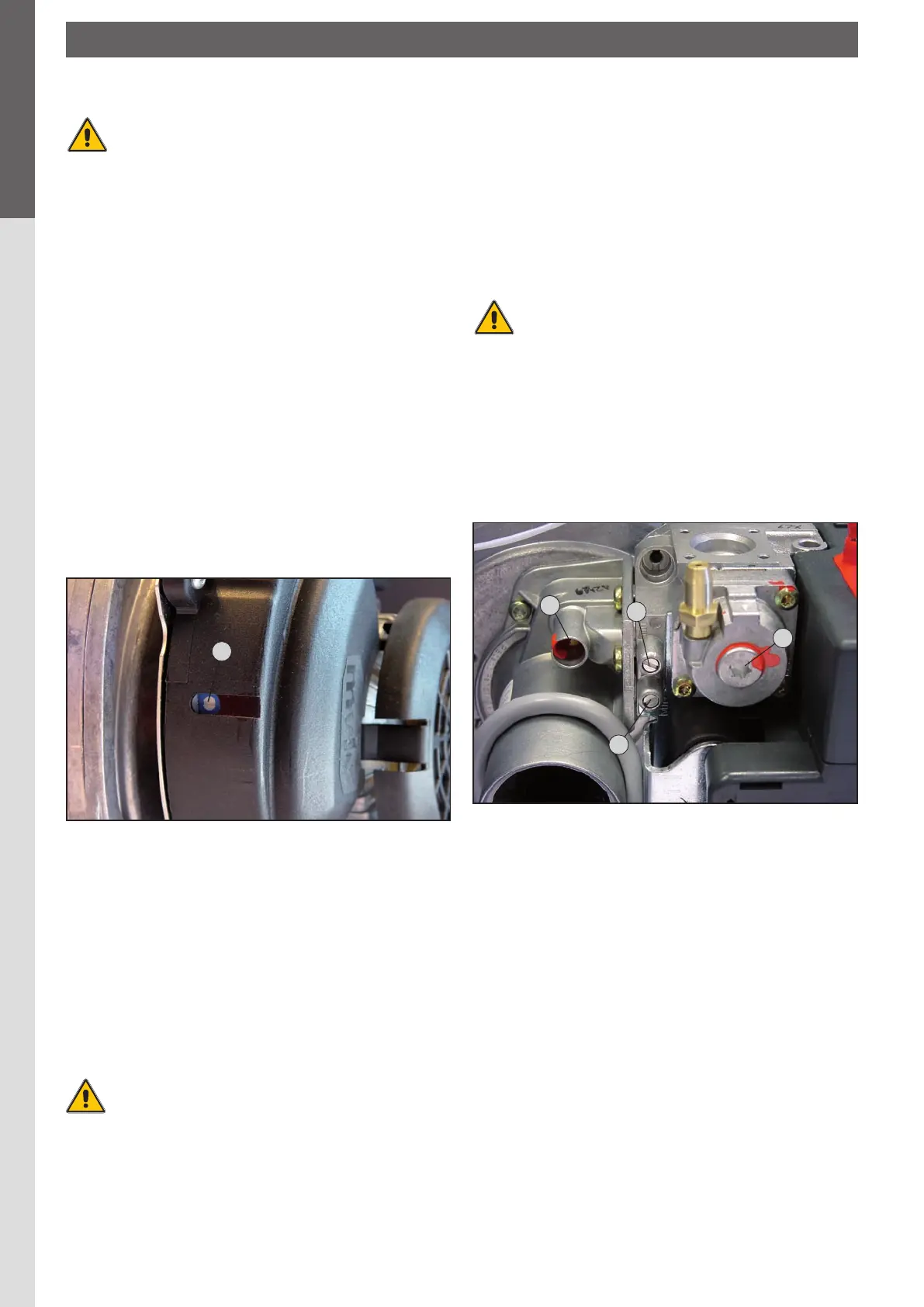
• Adjust the % of CO
2 to the figure shown in the table of setting
parameters on Page 17 by turning the gas flow adjuster screw
on the gas valve. (Fig. 16)
Turncounter-clockwise(moregas) ➠ increasesthe%ofCO
2.
Turnclockwise(lessgas) ➠ reducesthe%ofCO2.
The offset (4) is set at the factory and requires no
adjustment. Nevertheless ACV recommends that
youcheckthis setting. (Refer tothetable of setting
parameters).
You should contact your installer should you findany
significantdeviation.
1. Gas flow adjuster screw
2. Offset pressure measuring point
3. Upstream gas pressure measuring point
4. Offset adjuster screw cover
ELECTRODE DISTANCE AND GAP
BG 2000-S/SV
• Distance between ionisation electrode and tube :
A=10to15mm (refer to fig. 17)
• Distance between ignition electrode and tube :
B=2to5mm
(refer to fig. 18)
BG 2000-M/MV
• Distance between ionisation electrode and tube :
C=10to15mm (refer to fig. 19)
• Distance between ignition electrode and tube :
D=4to7mm (refer to fig. 20)
• Ignition electrode gap :
E=2to5mm
(BG 2000 M-MV : refer to fig. 21)
 Loading...