Data Port Connection
Data port cables, adapters and their applications are listed on pages 24
and 25.
¤ Connect the cable to the data port on the D-SERV back
panel. Secure the connector to the back panel with the
screws provided on the connector.
¤ Connect the other end of the cable to the DTE or DSU data
port, according to the manufacturer’s instructions.
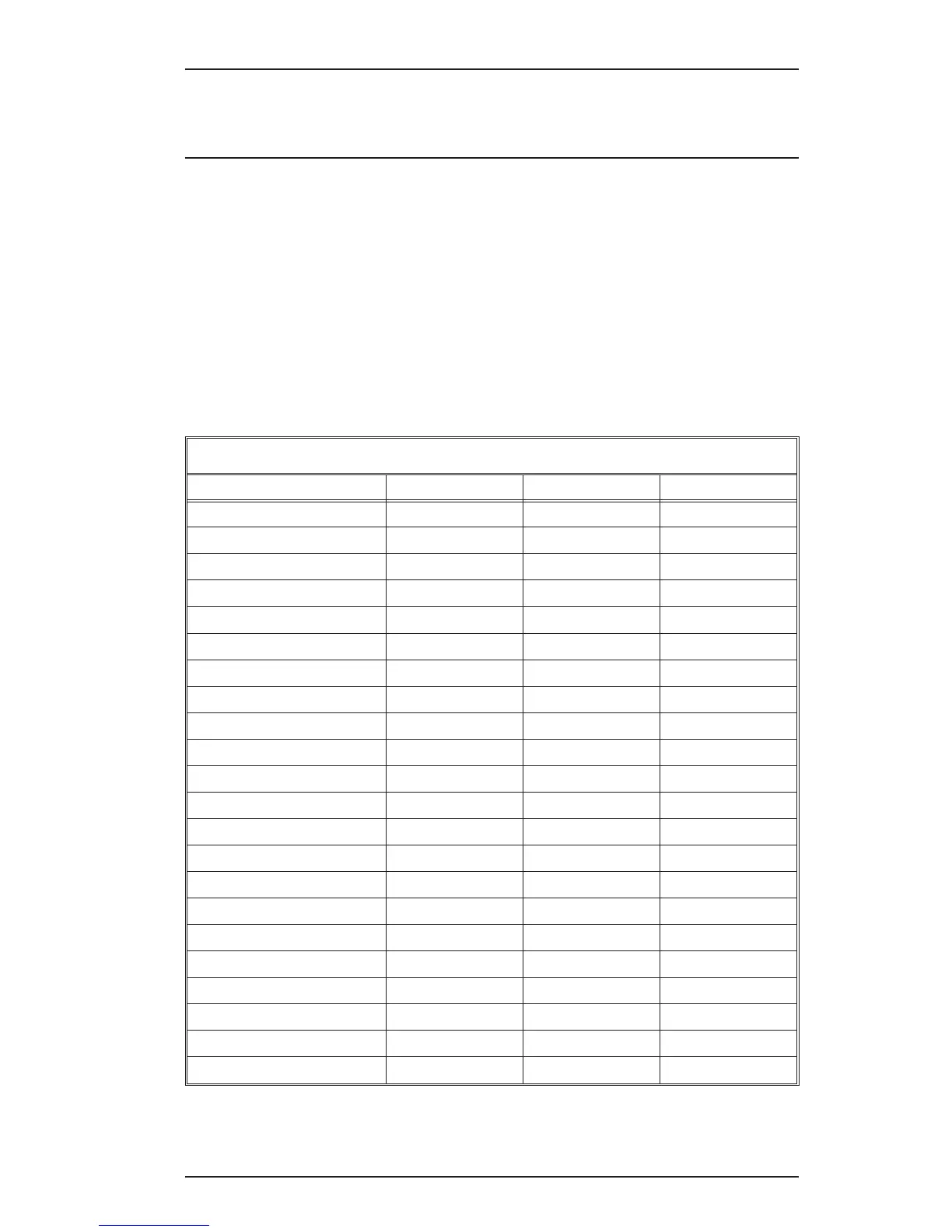
Data Port Pin Assignments
Circuit Name EIA-530 Pins V.35 Pins RS-449 Pins
Protective Ground 1 A —
Signal Ground 7 B 19
RTS 4, 19 C 7, 25
CTS 5, 13 D 9, 27
DSR 6, 22 E 11, 29
RI 22 — —
DTR 20, 23 H 12, 30
Rec Line Sig Det (DCD) 8, 10 F 13, 31
Tx Data A 2 P 4
Tx Data B 14 S 22
Rx Data A 3 R 6
Rx Data B 16 T 24
External Clk A 24 U 17 (DTE Source)
External Clk B 11 W 35
Tx Signal Timing A 15 Y 5
Tx Signal Timing B 12 AA 23
Rx Signal Timing A 17 V 8
Rx Signal Timing B 9 X 26
Local Loop Back 18 — 10
Remote Loop Back 21 — 14
Test Mode 25 — 18
Sig Gnd Return (530A) 23 — —
Operator's Manual
31

 Loading...