Adept SmartMotion Installation Guide, Rev B 9
List of Figures
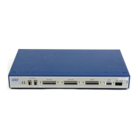
Figure 1-1. Adept sMI6 Module . . . . . . . . . . . . . . . . . . . . . . . . . . . . . . . . . . . . . . . . . . . . . . 11
Figure 2-1. Close-up of sMI6 LED Labels . . . . . . . . . . . . . . . . . . . . . . . . . . . . . . . . . . . . . . . 18
Figure 2-2. Adept sMI6 Module Front Panel . . . . . . . . . . . . . . . . . . . . . . . . . . . . . . . . . . . 19
Figure 2-3. Adept SmartMotion System Cable Diagram . . . . . . . . . . . . . . . . . . . . . . . . . 20
Figure 2-4. Opening the sMI6 Chassis . . . . . . . . . . . . . . . . . . . . . . . . . . . . . . . . . . . . . . . . 21
Figure 2-5. Location of Jumpers on Main PCA . . . . . . . . . . . . . . . . . . . . . . . . . . . . . . . . . 22
Figure 2-6. MP6-S Panel – Layout and Dimensions . . . . . . . . . . . . . . . . . . . . . . . . . . . . . 28
Figure 2-7. MP6-E Panel – Layout and Dimensions . . . . . . . . . . . . . . . . . . . . . . . . . . . . . 28
Figure 2-8. MP6-M Panel – Layout and Dimensions . . . . . . . . . . . . . . . . . . . . . . . . . . . . . 29
Figure 2-9. Typical System Wiring for One Axis of Motion . . . . . . . . . . . . . . . . . . . . . . . . 30
Figure 2-10. Encoder Input Circuitry . . . . . . . . . . . . . . . . . . . . . . . . . . . . . . . . . . . . . . . . . . . 41
Figure 2-11. Encoder Input Schematic . . . . . . . . . . . . . . . . . . . . . . . . . . . . . . . . . . . . . . . . 41
Figure 2-12. Single-Ended Encoder Wiring Using Inverted Outputs . . . . . . . . . . . . . . . . . 42
Figure 2-13. Single-Ended Encoder Wiring Using Non-Inverted Outputs . . . . . . . . . . . . . 42
Figure 3-1. SmartMotion System Installed to Control a User Mechanism . . . . . . . . . . . . 43
Figure 4-1. Dimensions for sMI6 Module . . . . . . . . . . . . . . . . . . . . . . . . . . . . . . . . . . . . . . . 47
Figure 4-2. Rack Mounting . . . . . . . . . . . . . . . . . . . . . . . . . . . . . . . . . . . . . . . . . . . . . . . . . 48
Figure 4-3. Panel Mounting . . . . . . . . . . . . . . . . . . . . . . . . . . . . . . . . . . . . . . . . . . . . . . . . . 48
Figure 4-4. Table Mounting . . . . . . . . . . . . . . . . . . . . . . . . . . . . . . . . . . . . . . . . . . . . . . . . . 49
Figure 4-5. Typical Input Circuit in sMI6 . . . . . . . . . . . . . . . . . . . . . . . . . . . . . . . . . . . . . . . 53
Figure 4-6. Typical Output Circuit in sMI6 . . . . . . . . . . . . . . . . . . . . . . . . . . . . . . . . . . . . . 53
Figure 4-7. Category 3 E-Stop Circuit . . . . . . . . . . . . . . . . . . . . . . . . . . . . . . . . . . . . . . . . 54
Figure 4-8. Category 1 E-Stop Circuit . . . . . . . . . . . . . . . . . . . . . . . . . . . . . . . . . . . . . . . . 55