Chapter 2 - System Installation
42 Adept SmartMotion Installation Guide, Rev. B
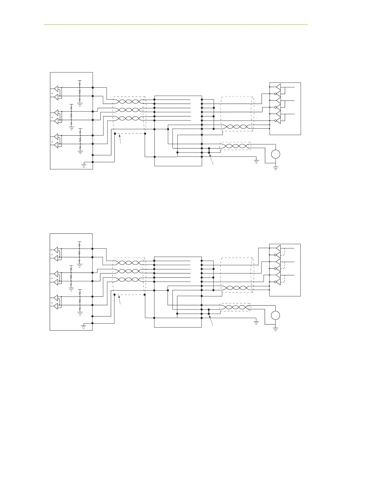
Single-Ended Encoders
Figure 2-12. Single-Ended Encoder Wiring Using Inverted Outputs
Figure 2-13. Single-Ended Encoder Wiring Using Non-Inverted Outputs
MP6-E
sMI6
Pin numbers
typical for encoder
channels 1 to 6
3
1
2
4
5
6
7
8
9
SHD
1
2
3
4
PWR
RTN
SHD
GND
+
–
User's
Encoder
Power
Supply
PWR
RTN
A–
A+
B+
B–
I+
I–
+
–
Encoder,
single-ended
I
A
B
Adept sMI6/
MP6-E Cable
SHLD
User-Supplied
Jumper
Note: this configuration will be highly sensitive to noise.
A–
A+
A
A
5V
B+
B–
I+
I–
+PWR
SHLD
5V
5V
B
B
I
I
MP6-E
Pin numbers
typical for encoder
channels 1 to 6
3
1
2
4
5
6
7
8
9
SHD
1
2
3
4
PWR
RTN
SHD
GND
+
–
User's
Encoder
Power
Supply
PWR
RTN
A–
A+
B+
B–
I+
I–
+
–
Encoder,
single-ended*
I
A
B
*Note: this configuration leads to inversion of the encoder channel
signals. Remember this when using the SPEC program to specify
the Zero-Index configuration.
Note: this configuration will be highly sensitive to noise.
Adept sMI6/
MP6-E Cable
SHLD
User-Supplied
Jumper
sMI6
A–
A+
A
A
5V
B+
B–
I+
I–
+PWR
SHLD
5V
5V
B
B
I
I