Chapter 2 - System Installation
30 Adept SmartMotion Installation Guide, Rev. B
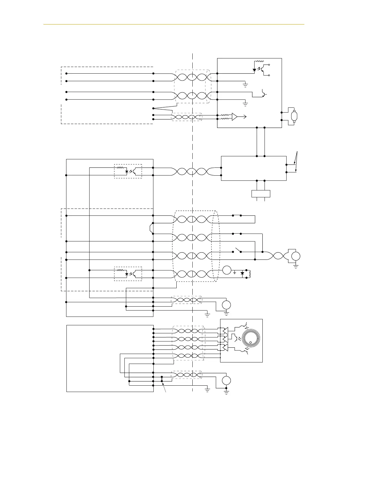
Figure 2-9. Typical System Wiring for One Axis of Motion
Customer's Hardware
Adept SmartMotion Hardware
Drive Amplifier
(Typical)
1
Drive
Enable
DE+
DE–
2
4DF+
DF–
5
Drive
Fault
+
+
Drive
Enable
Drive
Fault
1
High Power
Enable
HPE+
HPE–
2
MP6-S
MP6-M
Output
Input
1
Brake
Release
OT+
2
3
Positive
Overtravel
OT–
4
5
Negative
Overtravel
HM+
HM–
6
7
Home
BR+
BR–
8
Output
1
2
3
4
PWR
RTN
SHD
GND
9
SHD
Input
Input
Output
+
–
Typical
wiring for
one of six
axes
L1
L2
+
–
User I/O
Power Supply
User Power Supply
MP6-E
A–
A+
B+
B–
I+
I–
Encoder
+
–
Pin numbers
typical for encoder
channels 1 to 6
3
1
2
4
5
6
7
8
9
SHD
1
2
3
4
PWR
RTN
SHD
GND
+
–
User
Power
Supply
for Encoders
+
–
Brake Solenoid
PWR
RTN
Note: Opto-modules shown
as simplified equivalent
circuit only.
Line Filter
(recommended)
*
*
Commutating diode must be
used on all inductive loads.
(typical 1N4005)
Command
Signal
CD+
CD–
SHD
Analog Command
7
8
3
M
Motor
Output
Typical
wiring for
one of six
axes
User Logic
Power Supply
User-Supplied
Jumper
Emergency-Stop Power Cutoff
To SmartController
XUSR Connector
See pages 54 and 55 for examples of
this circuitry for various categories of
application safety requirements.