Typical Input and Output Circuits in sMI6
Adept SmartMotion Installation Guide, Rev. B 53
4.4 Typical Input and Output Circuits in sMI6
Input Circuits
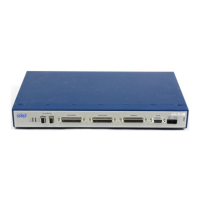
The circuit in Figure 4-5 is typical of all digital inputs on the sMI6 (3 per axis, 18 total):
•Home Switch
• Overtravel
•Drive Fault
Figure 4-5. Typical Input Circuit in sMI6
Output Circuits
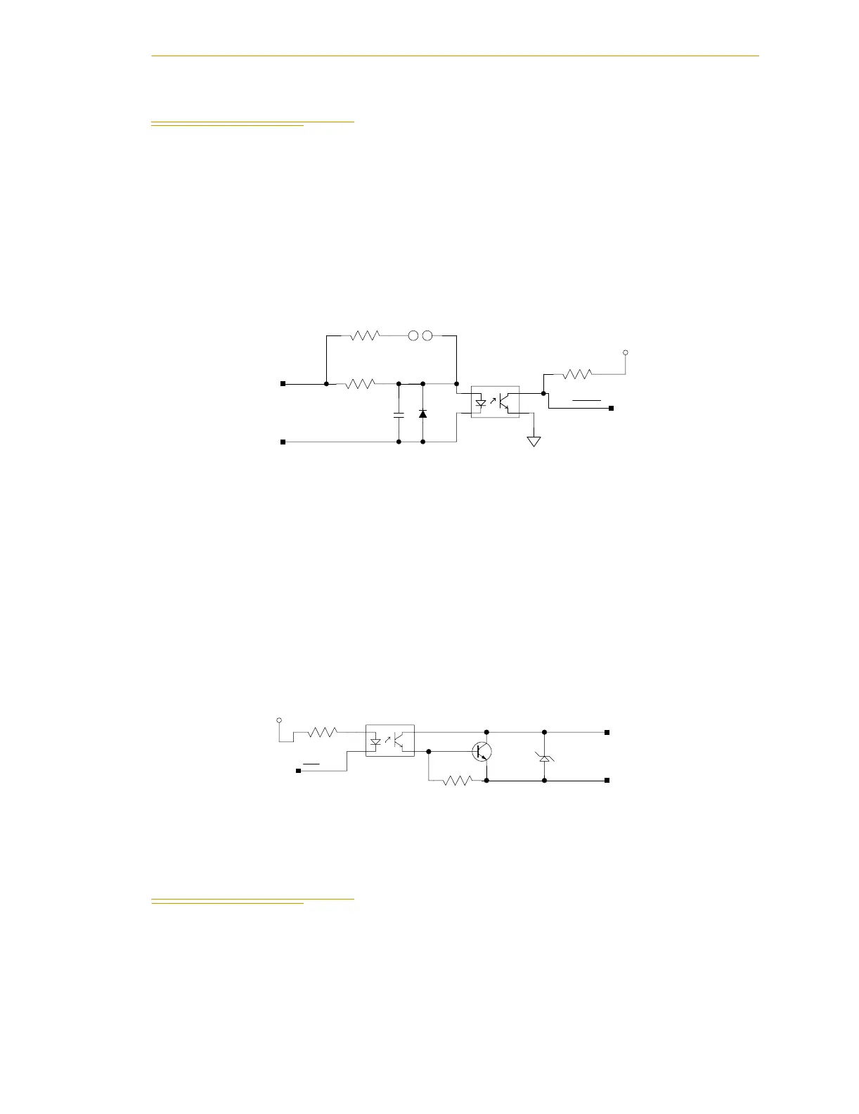
The circuit in Figure 4-6 is typical of all digital outputs on the sMI6 (2 per axis + 3, 15
total):
•Drive Enable
• Brake Release
• High Power Enable (HPE)
•Spares
Figure 4-6. Typical Output Circuit in sMI6
4.5 Emergency Stop Circuits
• Figure 4-7 on page 54 shows a Category 3 E-Stop circuit that can be created using a
PILZ PNOZ1 relay.
• Figure 4-8 on page 55 shows a Category 1 E-Stop circuit that can be created to cut
off power to the user amplifier.
3.3VD
R-0805
5%
BAS16L
D
TLP281-4
C-0805
C74
0.1UF
5%
R353
3.3K
R0603
25 26
JP_5V_ENA
1
2
16
15
U54
D10
2%
R-2010
2.7K
R122
R124
560
DR_FLT1
10/D3
DR_FLT1+
1/C5
DR_FLT1-
1/C5
3.3VD
R-0805
5%
27V
LP395FLT
TLP281-4
15
16
U16
1
2
3
Q7
5%
R162
4.7K
R0603
10/C1 BRE1
1
2
TVS10
BRE1-
1/D5
BRE1+
1/D5
200
R42
1
2