Adept SmartMotion Installation Guide, Rev. B 17
System Installation 2
2.1 Overview of Installation Process
This section provides a summary of the major steps involved with installing a Adept
SmartMotion system.
1. Verify that the default hardware configuration for the sMI6 module is correct for
your application. The area to look at is:
• Digital Input Logic Voltage - see page 21.
If you need to change these settings, you will have to open the chassis and install
or move jumpers.
2. Review the proper field wiring practices. See Section 2.5 on page 23.
3. Select an enclosure for the SmartController and sMI6 chassis. See Section 2.6 on
page 24.
NOTE: Refer to the system cable diagram in Figure 2-3 on page 20 for the
remaining steps in this process.
4. Install the SmartController and peripherals. See Section 2.7 on page 25.
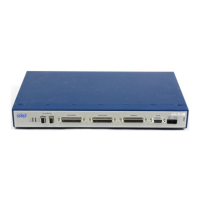
5. Install the sMI6 module. See Section 2.8 on page 25.
6. Install mounting rails for the three MP6 panels, then mount the three MP6 panels
on the rails. See Section 2.9 on page 26.
7. Connect cables from the sMI6 to the MP6-M, MP6-S, and MP6-E panels.
8. Install wiring to user equipment from the MP6-M and MP6-S panels. Also select
and install opto-modules. See Section 2.10 on page 31 and Section 2.11 on page
35.
9. Install wiring to user encoders from the MP6-E. See Section 2.12 on page 38.
When the above process is complete, the next step is to use the CONFIG_C and SPEC
utility programs to configure the software for your system. An overview for this process is
located in Chapter 3.

 Loading...