Emergency Stop Circuits
Adept SmartMotion Installation Guide, Rev. B 55
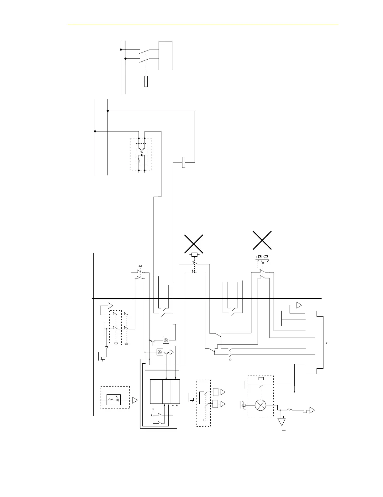
Figure 4-8. Category 1 E-Stop Circuit
Logic cyclic
check state
machines
Channel 1
Channel 2
ES1
ES2
Internal Connections
User Supplied Connections
E-Stop, High Power On/Off, and MANUAL/AUTO Controls for
CIM-2 Version of SmartController
FM
Front Panel
E-Stop
Enable
MCP
Channel 1
ESTOPSRC
Channel 2
User E-Stop Indication
User E-Stop and
Gate Interlock
(Jumper closed when
not used, MUST open
both channels
independently if used.)
ESTOPSRC
ES1
ES2
ES2
ES1
User Manual / Auto Indication
(Manual = Open)
MCP4
Enable
Switch
Manual/Auto
Enable
MM1
MM1
MM2
MM2
XUSER-22
XUSER-23
XUSER-10
XUSER-9
XUSER-17
XUSER-16
XUSER-3
XUSER-4
XUSER-20
XUSER-21
XUSER-8
XUSER-7
XUSER-15
XUSER-14
XUSER-1
XUSER-2
XFP-1
XFP-9
XFP-2
XFP-10
XUSER-6
XUSER-5
XUSER-18
XUSER-19
XSYS-9
XSYS-1
XSYS-7
XSYS-6
XSYS-3
XSYS-2
XSYS-5
Muted Safety Gate
- Active in auto mode
only
(Jumper closed when
not used)
ESTOPSRC
E-Stop
Auto 2
E-Stop
Manual 1
XSYS signals go to PDU or MAI-2 when required (No User Connection)
E-Stop
Reset
E-Stop
Auto 1
E-Stop
Manual 2
24 V
5 V
V
+
High
Power request
High
Power
On / Off
4.7
0.24V
XFP-6XFP-5
XFP-14
XFP-13
-
+
V
+
burned out
bulb notify
(prevents High
Power enable)
HP Light
Enable)
6V, 1.2 W
bulb
Front Panel
24 V
Front Panel
MM1
XFP-3
XFP-4
XFP-11 XFP-12
MM2
Manual/Auto Keyswitch
- Manual = Open (|)
- Manual => (<250 mm/s)
- Auto => 100%
24 V
5 V
Front
Panel
System
Power
LED
XFP-7
XFP-15
Grn
Jumper
See Note
Jumper
See Note
See Note
Note: These three functions:
Line E-Stop, Muted Safety Gate,
and MCP Enable, will only be
sensed by software. They will not
turn off High Power directly.
24 VDC
0 VDC
KA
+
HPE
MP6-M
–
Example CE EN495-1 Category B or 1
Emergency Stop circuit for Auto Mode,
showing simple power cutoff to
User Amplifier's High Power section.
This will enable High Power when
V+ calls for it.
L2
L2
L1
L1
User Amplifier
KA
Line E-Stop
(External User
E-Stop system)