Adept sMI6 Hardware Configuration
Adept SmartMotion Installation Guide, Rev. B 21
2.4 Adept sMI6 Hardware Configuration
sMI6 Digital Input Logic Voltage Configuration
The sMI6 can be configured to operate with either a 5V (min 3.0V, max 5.7V) or a 12/24V
(min 8.75V, max 27.5V) logic interface. This affects the Home, Overtravel, and Drive Fault
signals. The sMI6 is normally shipped configured for 12V input, and must be reconfigured
if you decide to operate at 5V. After you configure the sMI6 voltage option, then you must
install the MP6 Machine and Servo panels accordingly.
NOTE: Refer to Figure 4-5 on page 53 for a typical input circuit in the
sMI6.
The input voltage is determined by jumpers on the main printed circuit assembly (PCA)
inside the chassis. To reconfigure the sMI6 for 5V logic operation, follow this procedure.
1. Verify that the sMI6 is disconnected from the 24VDC power source.
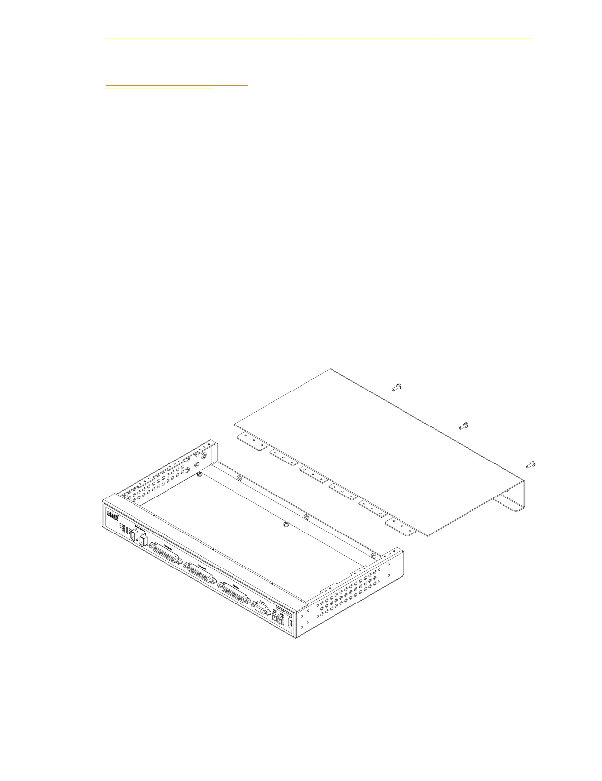
2. Remove the cover of the chassis by removing three screws at the back of the
chassis. See Figure 2-4.
3. Install jumpers for each channel that you are using. See Figure 2-5 on page 22.
4. Reinstall the cover on the chassis.
Figure 2-4. Opening the sMI6 Chassis