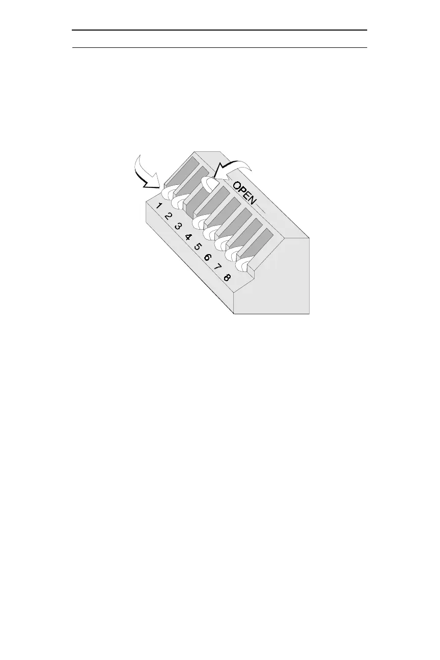
ADT-LCD40 Series Annunciators DIP Switch Settings Example
11
Document 50520 Rev D 7/25/00 P/N 50520:D
.
Note: SW1 DIP switch settings as illustrated in Figure 1-3 are as
follows:
1. DIP switch 1: On (Down) - Receive/Transmit. This setting is
used for the last or only ADT-LCD40 Series Annunciator on the
EIA-485 line
2. DIP switch 2: Used on ADT-LCD40 only - On (Down) = mem-
brane function switches enabled.
3. DIP switch 3: Off (Up) = piezo sounder disabled (requires
approval of LAHJ)
4. DIP switches 4 through 8: not used
Figure 1-3: DIP Switch Settings Example
Down Position = On State
Up (OPEN) Position = Off State
 Loading...