ADT-LCD40 Series Annunciators Typical Configuration
12
Document 50520 Rev D 7/25/00 P/N 50520:D
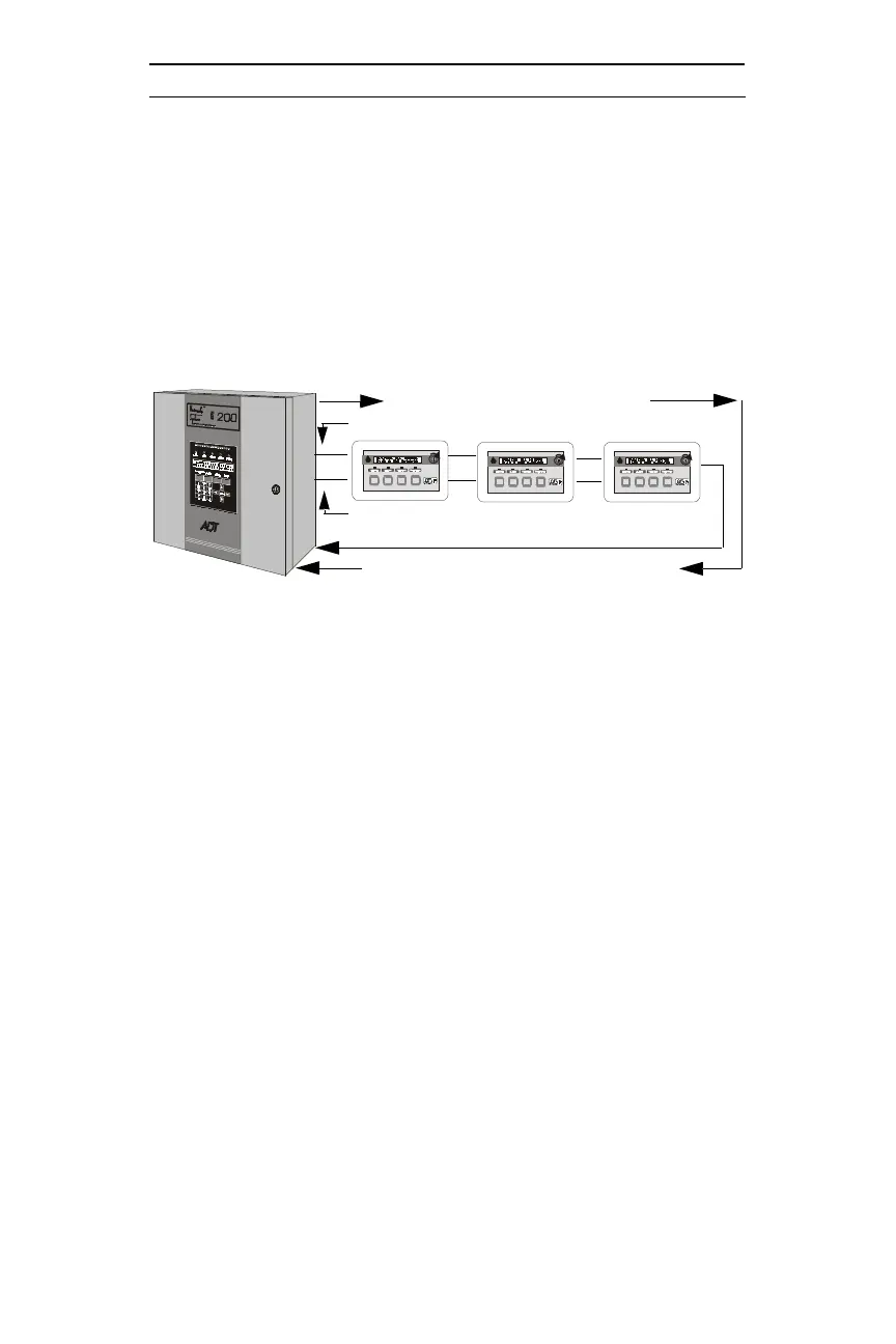
1.4 Typical Configuration
The ADT-LCD40 Series Annunciators mimic the Unimode 200 display,
have full point-display capacity and require no programming. The
ADT-LCD40 offers multiple annunciator locations with the capability
of remote Acknowledge, Signal Silence, Drill and Reset functions.
Notes:
1. EIA-485: maximum of 6,000 feet (1,800 m) total cable length
from FACP to annunciator and back to FACP for supervision
(3,000 feet [900 m] maximum to last ADT-LCD40). Circuit is
power-limited.
2. Up to 32 ADT-LCD40 Series Annunciators may be used on the
EIA-485 circuit. The Unimode 200 can power a maximum of
five annunciators. If additional annunciators are connected, the
FCPS-24F may be used to supply additional power. Power
supplies used for this purpose must have their negative terminals
commoned together.
3. Between each ADT-LCD40 Series annunciator are four wires - a
twisted shielded pair for data communications and a pair for 24
VDC power. The return circuit only requires two wires for data
communication supervision, wired from the last or only annunci-
ator on the line.
Ack Silenc e
Reset
Drill
Hol d 2 s e c.
FIRE ALARM ANNU NCIATOR
Ack Silenc e
Reset
Drill
Hol d 2 s e c.
FIRE ALARM ANNU NCIATOR
Ack Silenc e
Reset
Drill
Hol d 2 s e c.
FIRE ALARM ANNU NCIATOR
Figure 1-4: Typical Configuration
3,000 feet (900 m) to last device on loop
3,000 feet (900 m) back from last device on loop
Terminal Mode EIA-485 return (2 wires)
Terminal Mode EIA-485 (2 wires)
24 VDC (2 wires)