Mounting Semi-flush Mount Backbox
19
Document 50520 Rev D 7/25/00 P/N 50520:D
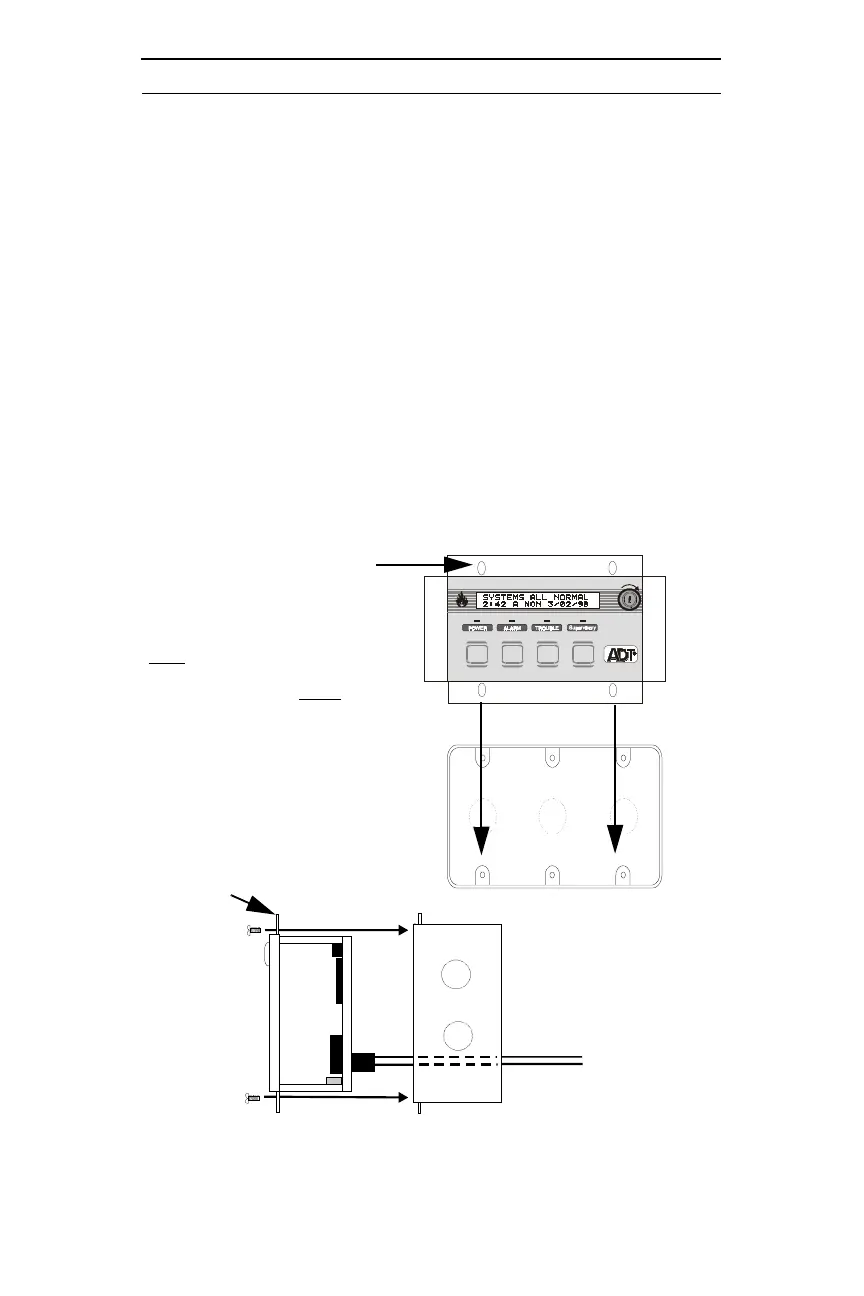
3.2 Semi-flush Mount Backbox
Remove the plug-in terminal blocks from the ADT-LCD40(L) circuit
board. Connect the EIA-485 and power wiring into the terminal block
positions illustrated in Figure 1-1 on page 8, Figure 4-1 on page 21 and
Figure 4-2 on page 22. Plug the terminal blocks back into the P1 and P2
connectors on the back of the annunciator. Set DIP switch SW1 for the
desired options (refer to Figure 1-2 on page 9).
Carefully insert the ADT-LCD40(L) into the three-gang electrical box
and attach it using the four mounting holes on the ADT-LCD40(L)
flange and the four screws provided for this purpose. Replace the trim
ring and secure with the two screws which were previously removed.
Adjust the plastic trim ring to the surface of the wall before tightening
the screws.
Do not overtighten.
Ack Silence
Reset
Drill
Hold 2 sec.
FIRE ALARM ANNUNCIATOR
Figure 3-3: Semi-flush Mounting
ADT-LCD40 Series flange
Mounting holes (4)
Three-gang electrical box
CAUTION! The ADT-LCD40 Series can
ONLY
be semi-flush mounted in a three-
gang electrical box, P/N 10103 or equiva-
lent, with a minimum depth of 2 3/16".
The ADT-LCD40 Series
cannot
be
mounted in three gangable electrical
switch boxes connected together.
ADT-LCD40(L)
Three-gang electrical box P/N 10103
flange
EIA-485 and power wiring