ADT-LCD40 Series Electrical Connections Wiring FACP to ADT-LCD40 Series
24
Document 50520 Rev D 7/25/00 P/N 50520:D
Dim-485 Installation.
CAUTION!
Connect all wiring to the DIM-485 terminals before
plugging it into connector J11 on the Unimode 200 circuit board.
1. Carefully align the DIM-485 connector with the four pins on
connector J11 of the Unimode 200
2. Press firmly on the DIM-485 connector to seat properly on
connector J11 being careful not to bend any pins
3. Be certain to secure the DIM-485 module to the Unimode 200
and keep all wiring from mechanically interfering with module.
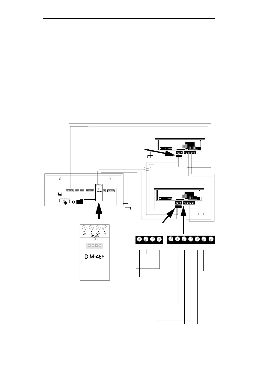
Figure 4-4: Wiring FACP to ADT-LCD40 Series
1 2 3 4
P1
P2
1 2 3 4
1 2 3 4 5 6 7
Ferrite Core P/N FBD-1
Required
Ferrite Core P/N FBD-1
Required
ADT-LCD40 Series in
grounded box
ADT-LCD40 Series in
grounded box
EIA-485
24 VDC
TB4 Terms
3(+) & 4(-)
DIM-485
Unimode 200
in grounded box
To p
(+) EIA-485
IN
(-) EIA-485
(+) (-)
EIA-485
OUT
(+) 24 VDC
IN
(-) 24 VDC
n/c
Earth
Ground
Optional
Shield
Connect
(+) (-)
24 VDC
OUT
Notes:
1) Ferrite Core P/N FBD-1 is required to meet
FCC Part 15 requirements if the EIA-485
wiring is not in conduit. Twisted, shielded
wire is recommended for the EIA-485
communications loop.
2) Six conductor overall shielded wire may be
used for the four EIA-485 wires and the two
power wires. It is, however, strongly
recommended that the power and communi-
cation wires be separate whenever possible.