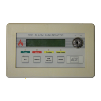
ADT-LCD40 Series Annunciators ADT-LCD40 and ADT-LCD40L
7
Document 50520 Rev D 7/25/00 P/N 50520:D
1.1 ADT-LCD40 and ADT-LCD40L
• 40-character LCD display (20 characters x 2 lines) is backlit
under normal and alarm conditions
• System Status LEDs for Power (green), Alarm (red), Trouble
(yellow) and Supervisory (yellow)
• No programming necessary — duplicates messages at control
panel display
• Local piezo sounder with alarm and trouble resound
• Device type identifiers from the control panel
• Device & zone custom alpha labels from the control panel
• Time/date and device address from the control panel
• EIA-485 connects to control panel terminal port (requires
DIM-485 module)
• Plug-in terminal blocks for ease of installation and service
• DIP switches control piezo enable/disable and transmit/receive
mode
• Up to 32 ADT-LCD40 Series Annunciators per Unimode 200
• Mounting options:
✓
Surface mounting in SBB-3 (2.75" depth)
✓
Semi-flush mounting in three-gang electrical box (P/N
10103) with a minimum depth of 2.187"
✓
Can be located up to 3,000 feet (900 m) from the panel
• Backlight turns off during AC loss to conserve battery power but
will turn back on if an alarm condition occurs.
1.2 ADT-LCD40 Only
• Enable/Disable key-switch
• Function switches for:
✓
Acknowledge
✓
Signal Silence
✓
Drill
✓
System Reset
• DIP switches control function switches and key-switch enable/
disable