ADT-LCD40 Series Electrical Connections DIM-485 Connections
23
Document 50520 Rev D 7/25/00 P/N 50520:D
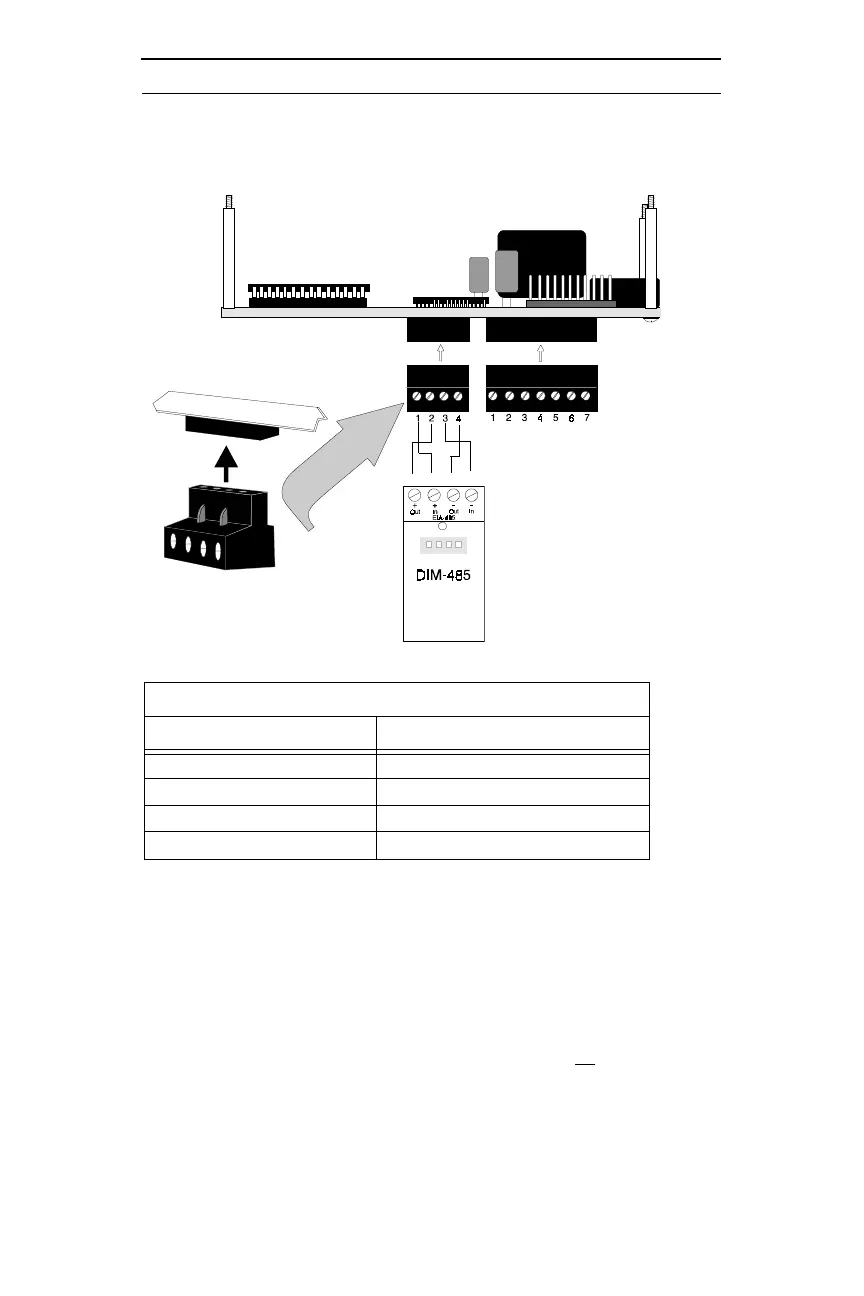
1. Terminal to terminal wiring is shown between the DIM-485 and
one ADT-LCD40 Series Annunciator
2. If more than one ADT-LCD40 Series Annunciator is installed,
the wiring to the DIM-485 In (+) Terminal 2 and In (-) Terminal
4 will be from the last installed annunciator (refer to Figure 4-4
on page 24)
3. The ADT-LCD40 Series Annunciators have resistors built into
the circuit board at the In (Terminals 2 & 4) and the Out (Termi-
nals 1 & 3) for impedance matching. There is no
need for the
installer to add impedance matching resistors
4. Connect wiring to DIM-485 terminals before plugging DIM-485
into connector J11 of the Unimode 200 main circuit board.
DIM-485 CONNECTIONS
DIM-485
ADT-LCD40 Series
3
Terminal 1 - OUT (+) P1 Terminal 2 - IN (+)
Terminal 2 - IN (+)
P1 Terminal 1
2
- OUT (+)
Terminal 3 - OUT (-) P1 Terminal 4 - IN (-)
Terminal 4 - IN (-)
P1 Terminal 3
2
- OUT (-)
Figure 4-3: DIM-485 Connections
Circuit Board
1 2 3 4
 Loading...