EasyManuals Logo

Adtech ADTECH9 Series User Manual

Adtech ADTECH9 Series
249 pages
To Next Page IconTo Next Page
To Previous Page IconTo Previous Page
Page #197 background imageLoading...
Page #197 background image
ADTECH9 Series CNC Maintenance Manual
- 192 -
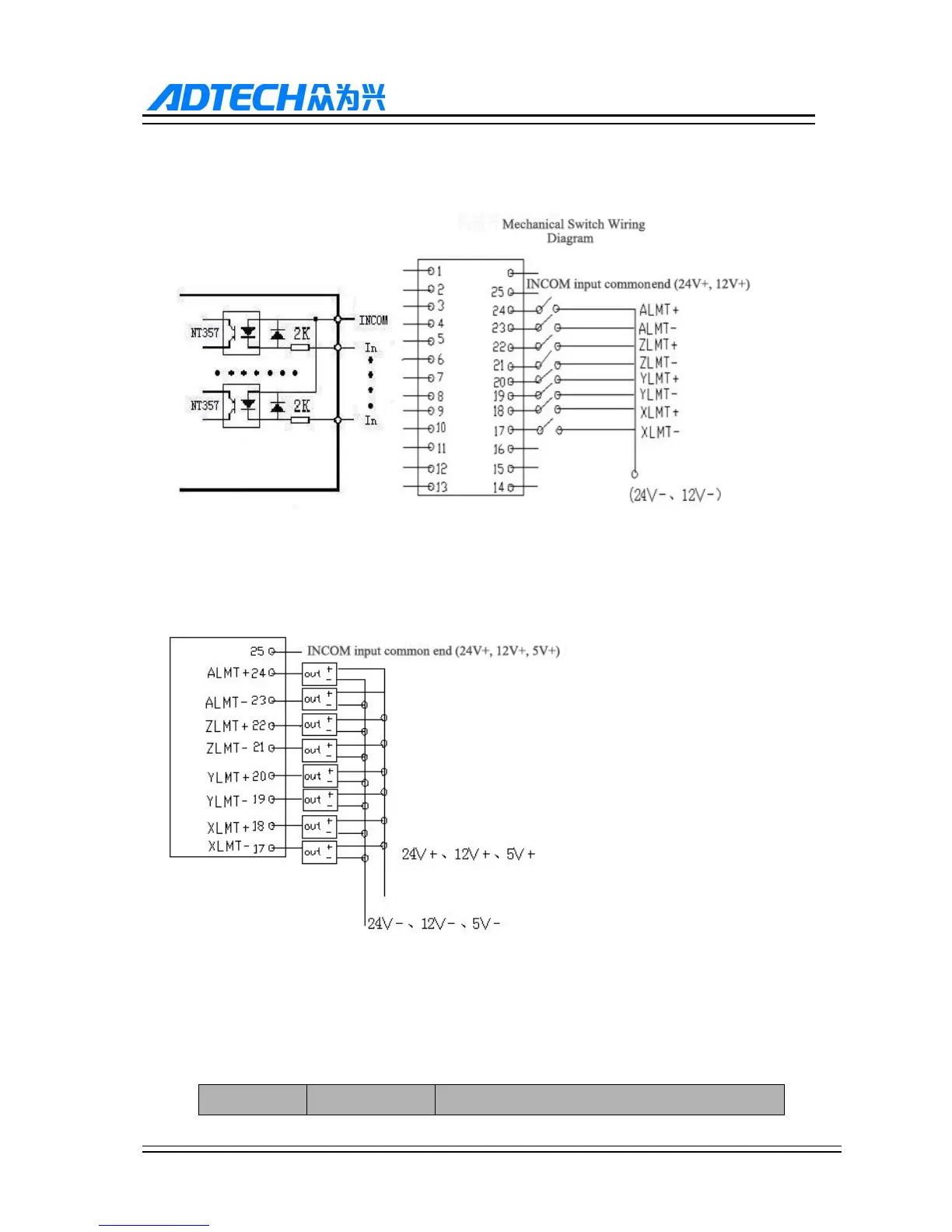
12.2.2. Digital input interface
The digital input interface contains the hardware limit signal of every axis, and the definition is as follows:
Simple Internal Output Diagram for Digital Input Photoelectric Switch Wiring Diagram
+ is the anode of approach switch, - is the earth wire, and OUT is output signal. For common approach switch,
please select 10-30V power supply and NPN output. Photoelectric switch is similar.
Default input port configuration of 96M series XS5 (CNC9640 milling machine)
Wire No. Port Definition Function

Table of Contents

Other manuals for Adtech ADTECH9 Series

Questions and Answers:

Question and Answer IconNeed help?

Do you have a question about the Adtech ADTECH9 Series and is the answer not in the manual?

Adtech ADTECH9 Series Specifications

General IconGeneral
BrandAdtech
ModelADTECH9 Series
CategoryControl Systems
LanguageEnglish

Related product manuals