ADTECH9 Series CNC Maintenance Manual
- 228 -
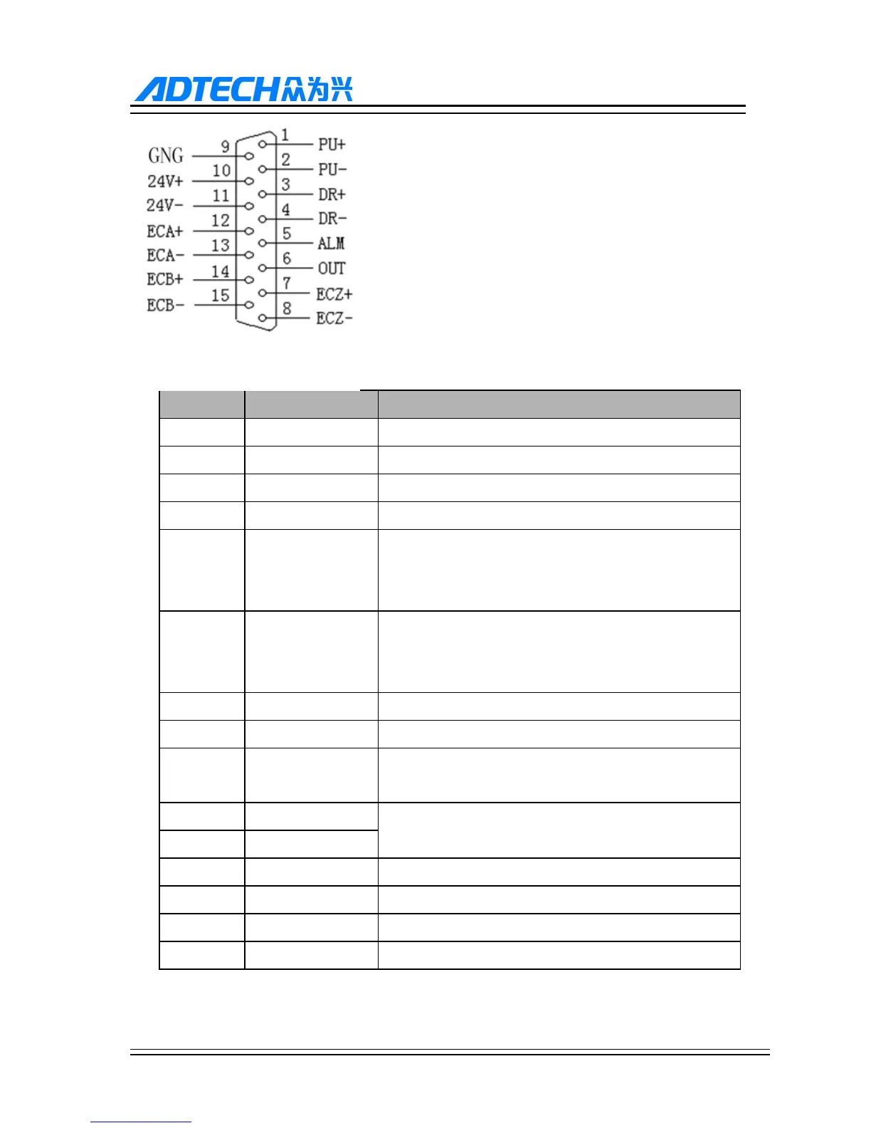
Wire No. Definition Function
1 PU+ Pulse signal +
2 PU- Pulse signal -
3 DR+ Direction signal +
4 DR- Direction signal -
5 ALM
Servo alarm signal input
X axis: IN66, Y axis: IN67, Z axis: IN68, A axis: IN69 , B
axis : IN70, C axis: IN71
6 OUT
Axis alarm reset output signal
X axis: OUT48, Y axis: OUT49, Z axis: OUT50, A axis:
OUT51 , B axis : OUT52, C axis: OUT53
7 ECZ+ Encoder phase Z input +
8 ECZ- Encoder phase Z input -
9 GND
99 series reference ground, 96 series single-ended to common
terminal
10 24V+
Internally provided 24V power supply, directly connected to
24V power supply of the controller
11 24V-
12 ECA+ Encoder phase A input +
13 ECA- Encoder phase A input -
14 ECB+ Encoder phase B input +
15 ECB- Encoder phase B input -
49 series pluse interface