E-6 ADAM 4000 Series User's Manual
RS-485 Network
Example:
Each input of the receivers has a nominal input impedance of 18 kW
feeding into a diode transistor- resistor biasing network that is equivalent to
an 18 kΩ input resistor tied to a common mode voltage of 2.4 V. It is this
configuration which provides the large common range of the receiver
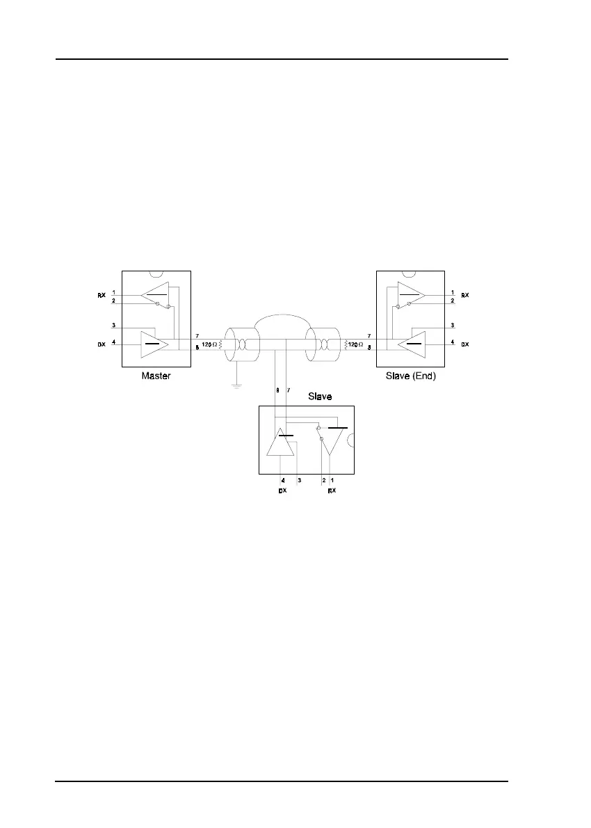
required for RS-485 systems! (See Figure E-5 below).
Figure E-5
Termination resistor locations
Because each input is biased to 2.4 V, the nominal common mode voltage
of balanced RS-485 systems, the 18 kΩ on the input can be taken as being
in series across the input of each individual receiver.
If thirty of these receivers are put closely together at the end of the trans-
mission line, they will tend to react as thirty 36kΩ resistors in parallel with
the termination resistor. The overall effective resistance will need to ne
close to the characteristics of the line.