EasyManua.ls Logo

Advantech Adam-4016 User Manual

Advantech Adam-4016
398 pages
To Next Page IconTo Next Page
To Previous Page IconTo Previous Page
Page #161 background imageLoading...
Page #161 background image
Chapter 4 Command Set 4-77
Chapter 4
4014D
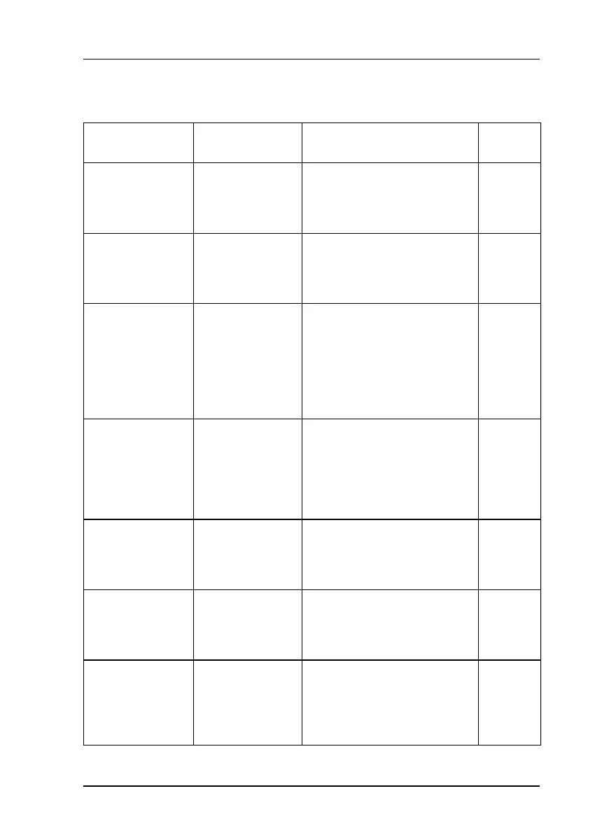
Command Syntax Command Name Description
I/O
Module
$AA3 Read Source
High/Low Values
for Linear Mapping
Read the high/low limit values
from the specified module for
linear mapping.
4014D
$AA5 Read Target
High/Low Values for
Linear Mapping
Read the mapped input high/ low
limit values from the specified
module for linear mapping.
4014D
$AA6
(data_A)(data_B)
Write Source
High/Low Values for
Linear Mapping
Write the high/low limit values to
the specified module for linear
mapping.
The module will only activate the
source values after new target
high/low values are written
(Command $AA7).
4014D
$AA7
(data_C)(data_D)
Write Target
High/Low Values for
Linear Mapping
Write the mapped input high/ low
limit values to a specified module
for linear mapping.
This command is only valid if its
was preceded by a $AA6
command.
4014D
$AAAV Enable/Disable
Linear Mapping
Enables or disables the linear
mapping function of the specified
analog input module.
4014D
$AA8V Select LED Data
Origin
Select whether LED will display
data from the input module
directly or from the host PC
4014D
$AA9(sign_data) Send LED Data The PC sends data to the
modules LED display. This
command is valid only after
selectting LED to display from PC
($AA8V)
4014D
4.4.2 Data Conversion and Display Command Set

Table of Contents

Question and Answer IconNeed help?

Do you have a question about the Advantech Adam-4016 and is the answer not in the manual?

Advantech Adam-4016 Specifications

General IconGeneral
Input Channels16
Analog InputYes
Resolution16-bit
CommunicationRS-485
ProtocolModbus RTU
Isolation Voltage3000 VDC
Input TypemV, V, mA
Input Range0 to 20 mA, 4 to 20 mA
Accuracy±0.1% of FSR
Sampling Rate10 samples/second (total)
Power Supply10 to 30 VDC
Operating Temperature-10°C ~ +60°C (14°F ~ 140°F)
Storage Temperature-25 ~ 85 °C (-13 ~ 185 °F)
Humidity10 ~ 95% RH (non-condensing)
Weight300 g

Summary

Chapter 1 Introduction

1.1 Overview

Provides a general description of the ADAM Series modules, their features, and power requirements.

Chapter 2 Installation Guideline

2.2 Basic configuration and hook-up

Explains the default factory settings and the basic procedure for configuring and connecting ADAM modules.

2.3 Baud rate and Checksum

Covers the process of setting the baud rate and enabling/disabling the checksum feature for reliable communication.

Chapter 3 I/O Modules

3.1 ADAM-4011/4011D/4012/4013/4015 Analog Input Modules

Describes the functionality and specifications of various ADAM analog input modules, including thermocouple and RTD types.

3.3 ADAM-4017/4017+/4018/4018M/4018+ 8-channel Analog Input Modules

Covers 8-channel analog input modules, including differential and thermocouple types, and data logger functionality.

3.6 ADAM-4050/4051/4052/4053/4055 Digital I/O Modules

Describes various ADAM digital I/O modules, including isolated and non-isolated types, and their channel configurations.

3.8 ADAM-4080/4080D Counter/Frequency Input Modules

Covers counter and frequency input modules, including programmable digital filters and thresholds for signal processing.

Chapter 4 Command Set

4.3 I/O Module Commands Search Table

Provides a comprehensive table listing commands for different I/O modules, including their syntax and function.

4.4 Analog Input Module Command

Details the command set specific to analog input modules, covering configuration, data reading, and calibration.

4.5 Analog Output Module Command

Outlines the commands for configuring and controlling ADAM analog output modules, including calibration and data output.

4.6 Digital I/O and Relay Output Module Command

Lists commands for controlling digital I/O and relay output modules, covering data input/output and status checks.

4.7 Counter/Frequency Module Command

Details commands for counter and frequency modules, including configuration, setup, and data retrieval.

Chapter 5 Calibration

5.1 Analog Input Module Calibration

Explains the software-based calibration procedures for ADAM analog input modules, including zero and span calibration.

5.3 Analog Output Calibration

Describes the process for calibrating ADAM analog output modules, focusing on setting output values for current and voltage ranges.

Appendix B Data Formats and I/O Ranges

B.1 Analog Input Formats

Explains the different data formats for analog input modules, including Engineering Units, Percent of FSR, and Twos Complement Hexadecimal.

Related product manuals