ARK-1124 User Manual 18
2.4.9 Antenna Hole
ARK-1124H reserves four antenna hole for wireless antenna installation. Each of
antenna hole mark “ANT” to let antenna hold easy to be recognized.
Figure 2.16 Antenna Hole
2.5 ARK-1124U External I/O Connector
2.5.1 Power On/Off Button
ARK-1124U has a Power On/Off button with LED indicators on the front side that
show On status (Green LED) and Off/Suspend status (Orange LED). The Power but-
ton supports dual functions: Soft Power -On/Off (Instant off or Delay 4 Seconds then
off) and Suspend.
Figure 2.17 Power On/Off Button
2.5.2 Power Input Connector
ARK-1124U comes with a DC-Jack header that carries 12 VDC external power input
Figure 2.18 Power Input Connector
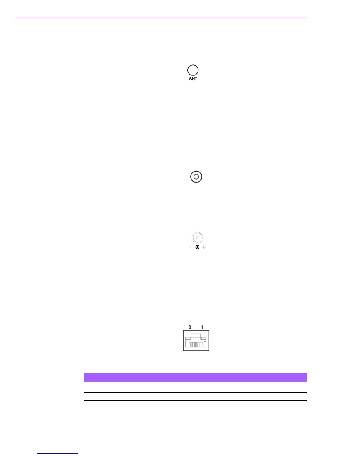
2.5.3 Ethernet Connector (LAN)
ARK-1124U is equipped with two Ethernet controllers that are fully compliant with
IEEE 802.3u 10/100/1000 Mbps CSMA/CD standards. LAN1, LAN2 are all equipped
with i210 Ethernet controller. The Ethernet port provides a standard RJ-45 jack con-
nector with LED indicators on the front side to show its Active/Link status (Green
LED) and Speed status (Yellow LED).
Figure 2.19 Ethernet Connector (LAN)
Table 2.7: Ethernet Connector (LAN)Pin Definition
Pin 10/100/1000 Mbps Signal Name
1 BI_DA+(GHz)
2 BI_DA-(GHz)
3 BI_DB+(GHz)
4 BI_DC+(GHz)