15 ARK-1550 User Manual
Chapter 2 Hardware installation
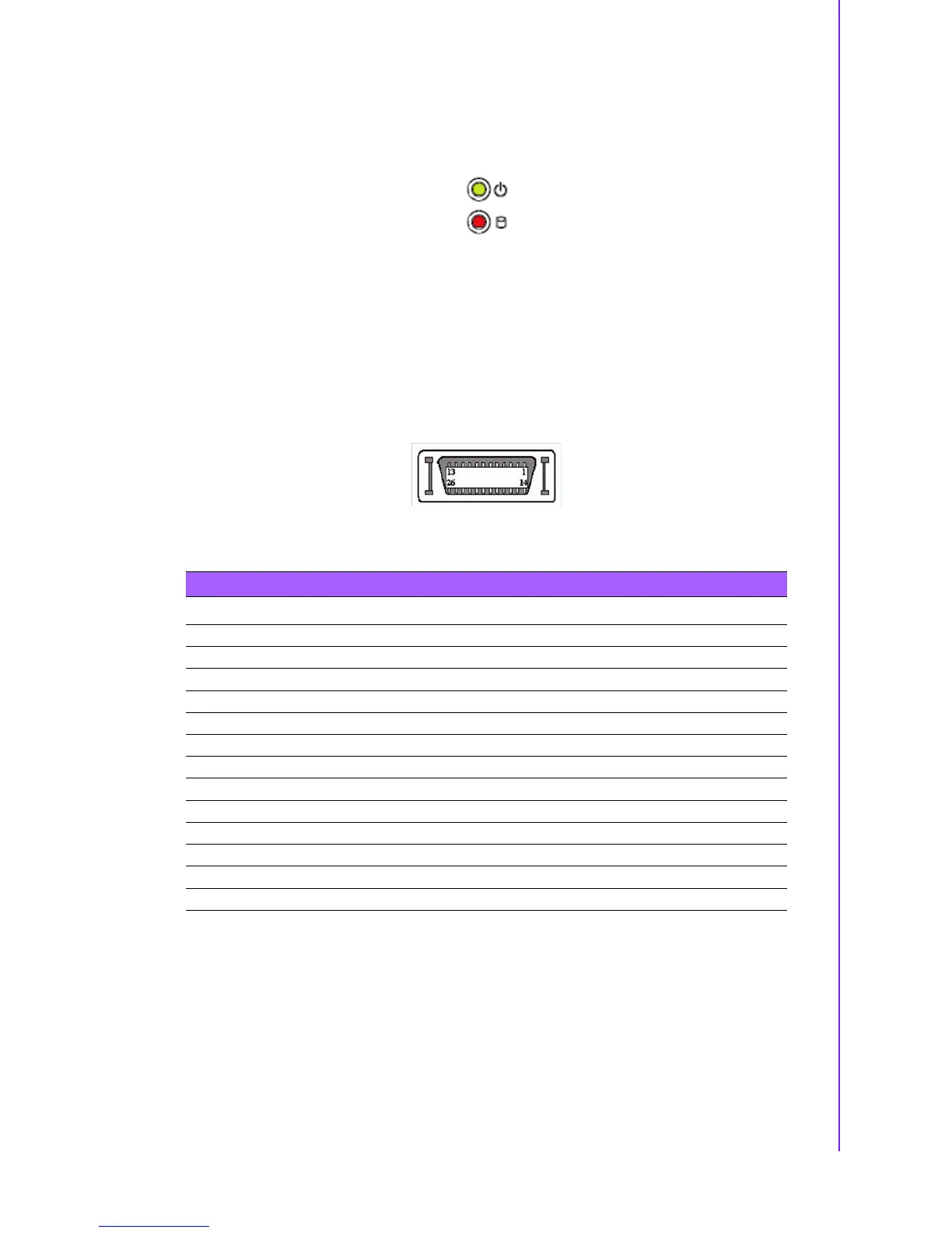
2.4.10 LED Indicator
There are two LEDs on ARK-1550 front metal face plate for indicating system status:
PWR LED is for power status; and HDD LED is for HDD flash disk status.
Figure 2.12 LED Indicator
2.4.11 LVDS Connector (Optional)
The ARK-1550 comes with a D-Sub 26-pin connector that carries LVDS signal out-
put, and can direct connect to LVDS LCD Display via external cable. The system also
provides a jumper J3 on the internal motherboard for selecting the LCD signal power
of 3.3V, 5V or 12V, please refer to the jumper table of J3 to adjust it. The default set-
ting of J3 is 3.3V.
Figure 2.13 LVDS Connector
Table 2.12: LVDS Connector Pin Assignment
Pin Signal Name Pin Signal name
1 LVDS_CLKBP 14 LVDS_CLKBM
2GND 15LVDS_YAM0
3 LVDS_YAP0 16 LVDS_YAM1
4 LVDS_YAP1 17 LVDS_YAM2
5 LVDS_YAP2 18 LVDS_CLKAM
6 LVDS_CLKAP 19 GND
7 3.3V, 5V or 12V 20 3.3V, 5V or 12V
8GND 21LVDS_YAM3
9 LVDS_YAP3 22 LVDS_YBM0
10 LVDS_YBP0 23 LVDS_YBM1
11 LVDS_YBP1 24 LVDS_YBM2
12 LVDS_YBP2 25 LVDS_YBM3
13 LVDS_YBP3 26 GND