Pin Assignments
A.2 Board Connectors and Switches
The UNO-2372G board features several connectors and jumpers. The following sec-
tions explain how to configure the UNO-2372G hardware.
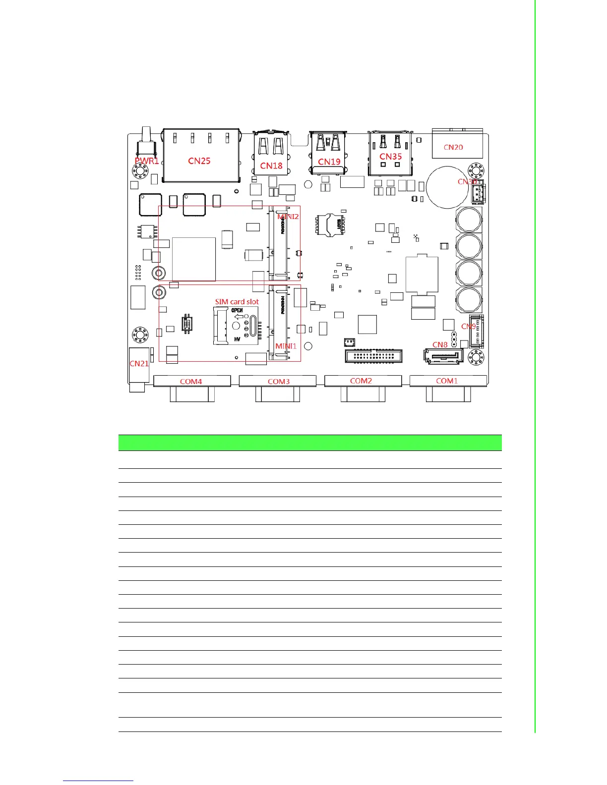
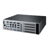
Figure A.1 shows the locations of the UNO-2372G connectors and switches.
Figure A.1 Connector and jumper locations (front)
Table A.2: Connectors and Jumpers
Label Function
CN20 Power input connector
CN35 HDMI connector
CN35 DisplayPort connector
CN18 2 x USB 2.0 connector
CN19 USB 3.0 and USB 2.0 connector
CN25 RJ45 connector
PWR1 Power button
RST1 Reset button
COM1 ~ 4 COM port connector
MINI1 PCI Express mini card socket (white connector)
MINI2 PCI Express mini card socket/mSATA (black connector)
CN8/CN9 SATA connector/SATA power connector
BH1 RTC battery connector
CN10 Internal GPIO pin header
CN21 Audio line-out
CN30 Internal power connector, voltage is the same as DCIN
SW1 AT/ATX mode switch. 1 OFF/ 2 ON -> ATX mode, 1 ON/ 2 OFF -> AT
mode
CN36 Clear COMS switch; Pins 2 ~ 1 -> normal, Pins 2 ~ 3 -> Clear