Switch-mode power supply AC2000 N1 / DC2000 N1 / AC3000 N1 / DC3000 N1 - Operating instructions
80001533 EFE en Page 14 of 41
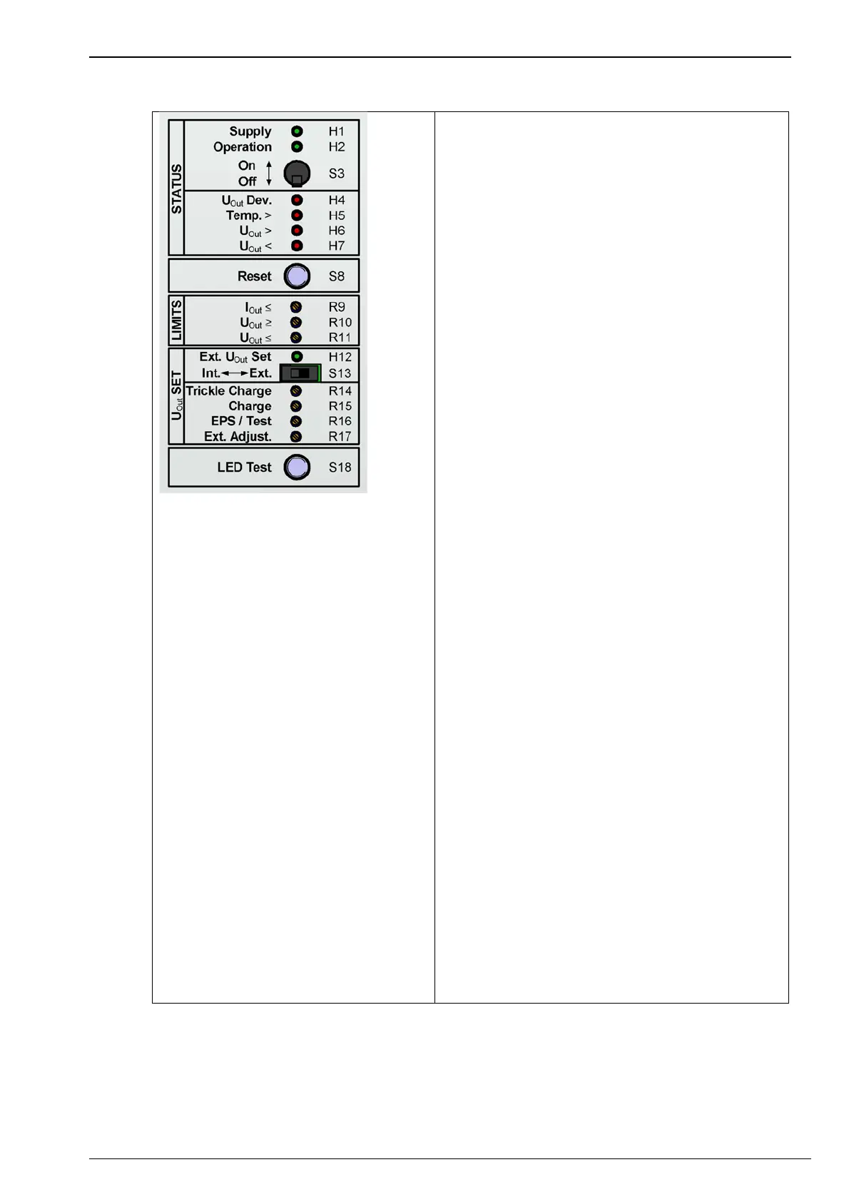
LED H1 (Supply)
Display: Mains voltage supply within the
tolerance range.
LED H2 (Operation)
Display: Power output.
Switch S3 (On/Off)
Switch the device on/off.
LED H4 (U
Out
Dev.)
Display: Deviation between setpoint and actual
value, indicator for current limitation.
LED H5 (Temp. >)
Warning: Overtemperature.
LED H6 (U
Out
>)
Fault: DC output overvoltage.
LED H7 (U
Out
<)
Fault: DC output undervoltage.
Button S8 (Reset)
Resets the device and the monitoring.
(section 6.2.8)
Potentiometer R9 (I
Out
)
Setting DC output current limitation.
Potentiometer R10 (U
Out
≥)
Setting overvoltage monitoring DC output.
(section 6.2.5)
Potentiometer R11 (U
Out
≤)
Setting undervoltage monitoring DC output.
(section 6.2.5)
LED H12 (Ext. U
Out
Set)
Display: External voltage setpoint setting active.
Switch S13 (Int./Ext.)
Internal/external voltage setpoint value
changeover.
(section 6.3.3)
Potentiometers R14-R17 (U
Out
Set)
Setting/adjusting the voltage setpoints.
(section 6.3.4)
Push-button S18 (LED test)
Test of all LEDs.
Note: The LEDs in the illustration show the
European colour scheme (Asian colour scheme
is available on request section 6.5).