Do you have a question about the AEP transducers MP2C and is the answer not in the manual?
Details F1 function for unload/peak, programmable Set Points with hysteresis, and digital filters for vibration attenuation.
Specifies the materials used for the instrument's case (NORYL UL94 V-O) and panels (UL94 V-2).
Describes the 8-bit microcontroller and the 20-bit sigma/delta Analog/Digital converter used in the MP2C.
Outlines the software's capabilities, including measurement management, digital filtering, and zero suppression.
Lists programmable resolution, Peak, Unload, Remote Inputs, Menu Lock, and Relay Output functions.
Outlines selectable input signals (current/tension) and output types (analog, serial, printer).
Lists default values for serial interface protocol, analog output, and instrument address.
Instructions for safely disconnecting the instrument from the electrical network.
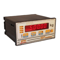
Details the functions of the 4 keys on the instrument's front panel for operation and menu navigation.
Describes the PRINT key's use for activating measurement reports and navigating menu options.
Explains the F1 key for Peak/Unload and the ENTER key for confirming data and advancing through menus.
Provides step-by-step instructions for accessing and modifying configuration parameters using the front panel keys.
Explains the process of setting parameter values using ESC, cursor keys (◄►), and ENTER.
Explains the process of setting parameter values using ESC, cursor keys (◄►), and ENTER.
Explains the process of setting parameter values using ESC, cursor keys (◄►), and ENTER.
Explains the process of setting parameter values using ESC, cursor keys (◄►), and ENTER.
Explains the process of setting parameter values using ESC, cursor keys (◄►), and ENTER.
Explains the process of setting parameter values using ESC, cursor keys (◄►), and ENTER.
Explains the process of setting parameter values using ESC, cursor keys (◄►), and ENTER.
Explains how to activate/deactivate the Menu Lock function using a specific password.
Allows suppressing the fixed tare generated by the load cell structure, setting it as system zero.
Explains the HOLD function, activated via remote digital input, to lock the instrument display.
Check the exact supply voltage specified on the identification plate before connecting.
Perform electrical connections for power, load cells, and transducers as per diagrams and markings.
Power the instrument and allow it to reach thermal stability for approximately 30 minutes.
Verify that the indicator's full scale matches the load cell or transducer's nominal rate.
Deduct any fixed tare present in the system as part of the installation procedure.
Provides guidance on creating the panel cutout and securely mounting the instrument using supplied accessories.
Provides information on safe transport practices and the instrument's state upon delivery.
Displays the typical layout and information found on the instrument's identification plate.
| Brand | AEP transducers |
|---|---|
| Model | MP2C |
| Category | Measuring Instruments |
| Language | English |