53
English
The place of assembly must be selected
in a way that the maximum and mini-
mum room temperature limit is respec-
ted 0÷45°C (<85% U.R.).
Follow the precautions given below
when installing the unit:
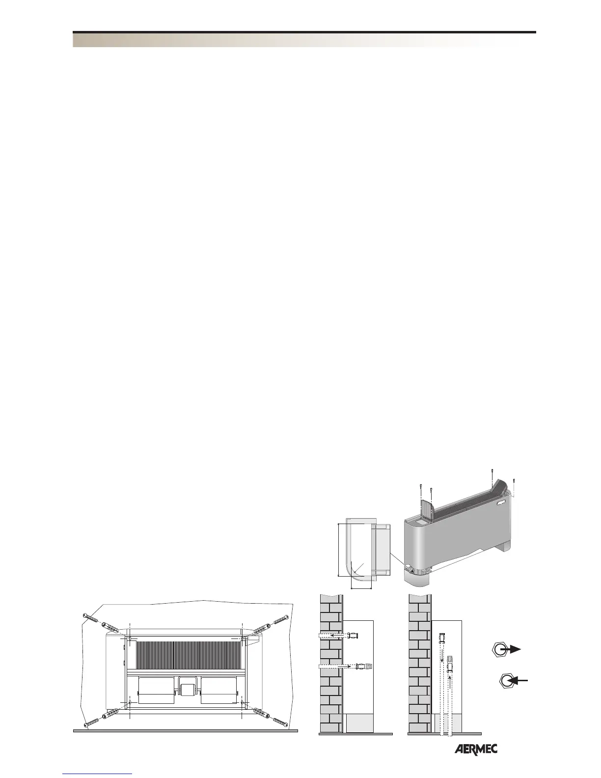
- In wall installation, maintain a mini-
mum distance from the floor of 80
mm. In the case of floor installation
using skirting, refer to the instructions
supplied with the accessory.
- For wall fixing, use expansion plugs
(not supplied)
- Make the hydraulic connections.
The position and diameter of the
hydraulic connections are stated in the
dimensional data.
It is advised to suitably insulate the
water pipes or to install an auxiliary
condensate collection basin, available
as an accessory, in order to prevent
dropping during functioning in cooling
mode.
The condensate drain network must
be appropriately dimensioned and the
piping positioned in a way to main-
tain an adequate slope along the route
(min.1%). In case of draining into the
sewer system, it is recommended to
realise a siphon that prevents nasty
smells from returning towards the
rooms.
- Apply any accessories.
If the 3-way VCF valve is installed, the
water probe SW must be replaced with
accessory SW3, whose bulb will be
applied on the delivery pipe upstream
from the valve.
The VCF valve and the basin BC4 can-
not be installed at the same time on
the same fan coil.
- Make the electric connections accor-
ding to that stated in the wiring dia-
grams and in the “Electric connec-
tions” chapter.
- To modify the settings of the electronic
thermostat act on the Dip-Switches
positioned inside the panel (see instal-
lation manual).
- Re-mount the cover, without forget-
ting, that for models that have one,
to connect the room probe that must
project outwards by about 3mm from
the probe-holder and must be well-
fixed using the relevant probe-block.
- Re-position the air filter.
- Check the correct functioning of the
fan and any accessories.
Some models with electronic thermo-
stat, by means of the Autotest proce-
dure, allow to check correct functio-
ning. The function is described in the
manuals supplied with the unit.
Electric connections
The electric circuits are connected to the
mains voltage of 230V ~ 50Hz; all con-
nections and components must therefore
be isolated for this voltage.
FEATURES OF THE CONNECTION
CABLES
Use cable type H05V-K or N07V-K with
300/500 V insulation recessed in a pipe or
channel. All cables must be recessed in a pipe
or channel until they reach the fan coil. The
cables exiting the pipe or channel must be
positioned in a way as not to undergo stress
from traction or twisting and, however, pro-
tected from external agents
For all connections, follow the wiring dia-
grams supplied with the appliance and stated
in this documentation.
To protect the unit against short circuits,
mount a magnet omnipolar switch 2A
250V (IG) on the power supply line with
a minimum opening distance of the con-
tacts of 3mm.
Every control panel can control just one
fan coil.
WARNING: the probes have double
insulation as they are exposed to a vol-
tage of 230Vac.
INFORMATION FOR THE INSTALLATION
A
A
B
B
A
B
167 mm
65 mm
49 mm
ZX
WARNING: check that the power sup-
ply is disconnected before performing
operations on the unit.
WARNING: before carrying out any
interventions be prepared with suitable
I.P.D.
WARNING: The appliance must be
installed in compliance with national
system regulations.
WARNING: wiring connections installa-
tion of the fancoil and relevant accesso-
ries should be performed by a technician
who has the necessary technical and
professional expertise to install, modify,
extend and maintain plants and who is
able to check the plants for the purpo-
ses of safety and correct operation.
WARNING: Install a device, master
switch or plug that allows to completely
interrupt the appliances electric power
supply.
Here, find the indications essential for
correct installation of the appliances.
Leave processing of all operations to the
experience of the installer, according to
specific requirements.
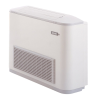
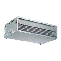
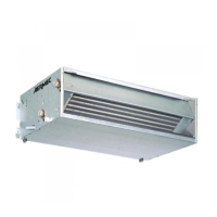
The fan coil must be installed in a posi-
tion such that the air can be distributed
throughout the entire room and there are
no obstacles (curtains or objects) to the
passage of the air from the intake grills.
The fan coil must be installed in a posi-
tion such to allow easy routine (cleaning
the filter) and extraordinary maintenan-
ce, as well as access to the air vent valve
on the side of the frame (connections
side).
The installation must not constitute a
danger for persons.
UNIT INSTALLATION