8
English
COMPONENTI PRINCIPALI
CONTROL PANEL
The control panel is located under the
grill positioined at the right of the fan
coil.In A, AS, ACB, ACT, APC and U
(62U, 82U e 102U) versions, the panel
can be protected from tampering by
using a screw to block the cover door.
In the AS and U versions, the controls
panel (accessory) can be installed on the
fan coil or on the wall.
In versions P, PO and PE, the controls
panel (accessory) can be installed only
on the wall.
The AERMEC fan coil versions without
control panels can be combined to a
HSH AERDOMUS central control unit
with or without connection cables.
Before selecting, consult the control
panels features.
FCX A
WITH MANUAL SELECTORS :
fan coil equipped with control panel for
use and selcting the fan speed.
FCX ACT e APC
WITH ELECTRONIC MULTIFUNCTION
THERMOSTAT :
fan coils equipped with multifunction
electronic thermostat control panels,
the fan coils FCX ACT and FCX APC
are supplied ready for use with standard
configuration, but the installer can adapt
them the special requirements of the
system with the appropriate accessories
and personalising the functions by acting
on the internal Dip-Switch.
The controls are prompt but if valves are
presence they could delay.
System types
The FCX-ACT fan coils have been
designed for systems with 2 pipes, in the
following versions:
- without valve;
- with water valve (VCF);
- with electrical resistance (RX);
- with electrical resistance (RX) and valve
(VCF);
- with hot water battery (BV) and 2 valves
(VCF).
FCX APC : fancoils with
PLASMACLUSTER designed for 2-pipes
plant, in the following models:
- without valve;
- with water valve (VCF);
Ventilation
The three-speed ventilation can
be controlled either manually or
automatically.
For systems with valve and Water Probe
installation upstream of the valve there
may be a delay (delayed ventilation up
to 2’40” max) between the valve start-up
and the fan activation (exchanger pre-
heating).
- manually with the selector in V1, V2 e
V3 position (the fan coil is used with on
off cycles on selected speed);
- automatically with the selector
in AUTO position (the fan speed is
controlled by the thermostat according
to the room temperature)
Change over
The thermostat automatically changes
over from Heating/cooling mode.
Change over is based on the water
temperature detected in the system. It is
possible to choose between two change
over modes by changing the settings on
the DIP switch :
- only minimum/maximum temperature
control;
- with minimum/maximum temperature
control and the preheating of the coil
(fan delayed for a maximum of
2’40”).
Only systems with water probes
positioned downstream of the valve
or with a two way valve,
change over
occurs on the air side by acting on
the temperature selector; this setting
allows the fan coil to be used in
systems with two way valves
but is not
advised because it reduces the use of
the electronic thermostat (the heating/
cooling modes displayed by the led
are altered depending on the selected
temperature and of the air temperature
in the environment.
Water temeperature controls
The thermostat enables
ventilatsolamenteon only if the water
temperature is suited to Hetaing or
Cooling mode.
The enabling threshold is 35°C or
39°C for Heating and 17°C or 22°C for
Cooling and can be configured by the
Dip-Switch.
The control panels signal the situation
when the water temperature is not
adequate to the function mode set by
means of the alternate flashing of the
pink C led with red or blue depending
on the relative active modes.
If a three way valve is inserted with a
water probe as per standard, it must be
replaced with the SW3 accessory in
which the bulb must be positioined on
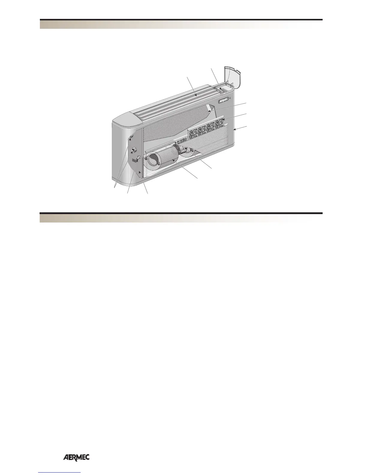
DESCRIPTION OF COMPONENTS
1
2
3
4
5
6
7
8
9
10
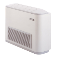
FCX 42 U
1 Control panel (accessory)
2 Thermic exchange coil
3 Air Filter
4 Cover cabinet (RAL9002)
5 Fan motor
6 Fan
7 Main Frame
8 Condensate pump
9 Hydraulic connections
10 Head with adjustable fins (RAL7044)