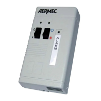
PR3 SIMPLIFIED REMOTE CONTROL PANEL
Allows to take the basic controls (switch-
on/off, change functioning mode, alarm
signals) away from the unit. The maxi-
mum installation distance allowed is
150 m for the units with moducontrol
circuit board. For units without modu-
control and connections exceeding 30
m couple the SDP accessory that allows
connections up to 150m between the
unit and the PR3.
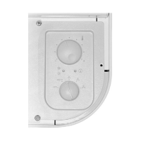
Notes regarding installation:
• For the wall installation of the PR3, see
fi g. 1-2-3.
The connection cable must be in-
stalled separately from the other sys-
tem lines in order to prevent interfer-
ence to the signals.
32
130
76
A
L
A
R
M
fi g.1
fi g.2
Functioning in cooling mode:
The PR3 panel has priority over the con-
trols on the machine. Unit switch-on/off
is commanded from the PR3 simplifi ed
remote control panel. It is only possible
to command switch-on/off from the pan-
el on the machine when the switch (2)
on the PR3 is in the ON position.
Functioning in heat pump mode
The PR3 panel has priority over the con-
trol panel on the machine. Unit switch-
on/off and the cooling/heating function-
ing modes are commanded from the
PR3 simplifi ed remote control panel. It
will be possible to command switch-on/
off from the panel on the machine only
when the switch (2) on the PR3 is in po-
sition ON. The heating/cooling function-
ing mode that is already set using the
switch (4) on the PR3 simplifi ed remote
control panel cannot be changed.
fi g.3
Description of components:
1 - PR3 simplifi ed remote panel
2 - ON/OFF switch
3 - Yellow ON/OFF indicator (Yellow LED on = ON)
4 - COOLING/HEATING functioning mode switch-over
❊= functioning in heat pump mode
❄= functioning in cooling mode
5 - Two-colour indicator, indicates the functioning mode
Red = the heat pump is functioning
Blue=it is functioning in cooling mode
6 - Red indicator, on indicates the alarm status
8
PR3_new.indd 8 24/06/2009 12.07.58