Subject to Export Control, see Cover Page for details. 2-23
D. RF Power Meter Verification
TEST EQUIPMENT: RF Signal Generator
RF Power Meter
RF Power Amplifier (50 W)
Coupler
100 MHz Low-Pass Filter
300 MHz Low-Pass Filter
700 MHz Low-Pass Filter
1200 MHz Low-Pass Filter
50 Ω Termination
10 dB Attenuator (50 W)
The following steps must be performed in the order shown.
RF COUPLED PORT ATTENUATION
1. Zero and calibrate the RF Power Meter.
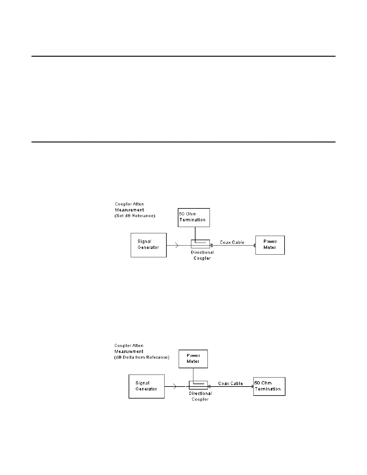
2. Connect test equipment:
3. Set the RF Signal Generator to 100 MHz, CW and 0 dBm.
4. Set the RF Power Meter to 100 MHz.
5. Press Relative on the RF Power Meter to reference the output power level at the end of
the coaxial cable.
6. Move the Power Sensor to the Coupler’s forward-coupled port and move the 50 Ω
Termination to the end of the coaxial cable: