2-24 Subject to Export Control, see Cover Page for details.
D. RF Power Meter Verification (cont)
7. Record the RF Power Meter relative dB value for 100 MHz:
Coupled Port Attenuation (dB)
100 MHz
300 MHz
500 MHz
700 MHz
900 MHz
8. Repeat Steps 2 to 7 for 300 MHz.
9. Repeat Steps 2 to 7 for 500 MHz.
10. Repeat Steps 2 to 7 for 700 MHz.
11. Repeat Steps 2 to 7 for 900 MHz.
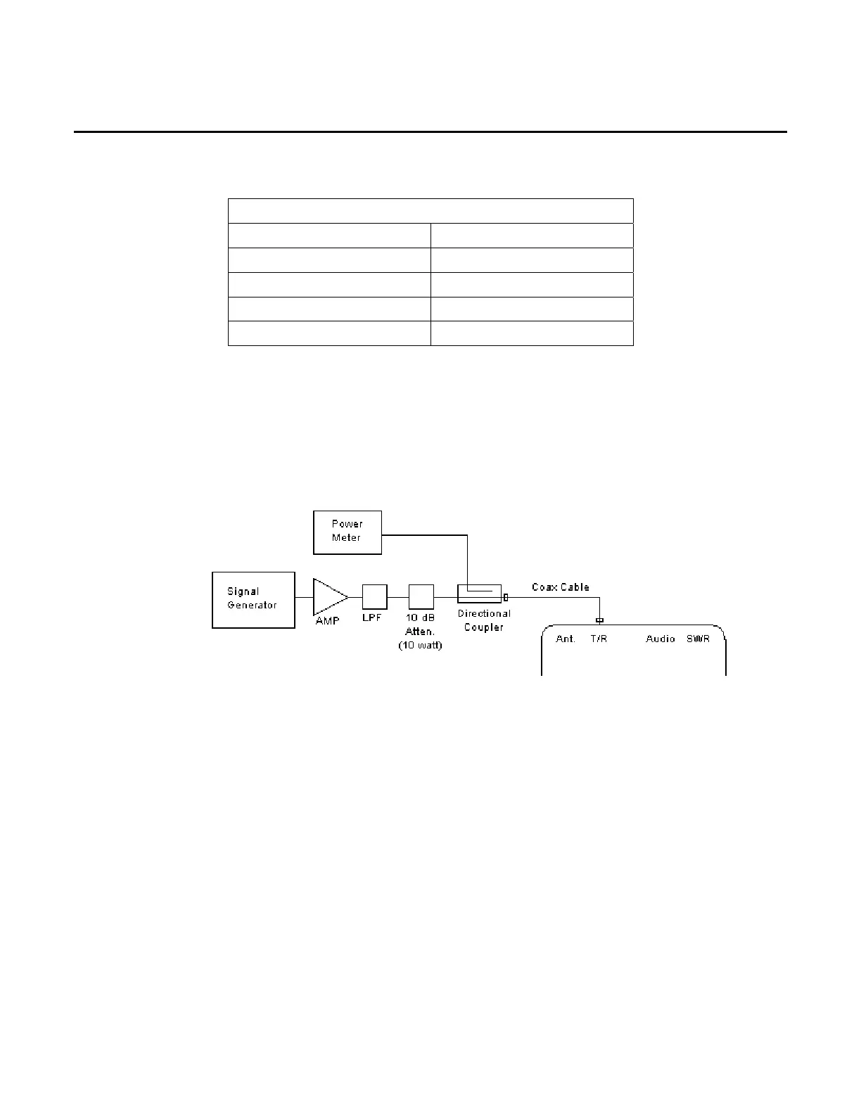
12. Connect test equipment (using 100 MHz Low-Pass Filter):
13. Set the RF Signal Generator to 100 MHz, CW, -50 dBm and RF OFF.
14. Set the RF Power Meter to 100 MHz, Relative OFF and Offset value to 100 MHz coupled
port attenuation recorded in Step 7.
15. Set RF Power Amplifier Gain to Maximum and ALC to OFF.
16. Set the RF Power Amplifier to OFF.
17. With the System Menu displayed, press the 3 Key to display the Transmitter Test Screen.
18. Move the cursor to the MHz: field.
19. Press the F1 “Edit” Key to highlight the field. Press the 1 Key and 0 Key twice to set the
field to 100 MHz. Press the F1 “Done” Key to store the setting.
20. Move the cursor to the Port: field.
21. Press the F1 “Edit” Key to highlight the field. Using the Arrow Keys ( ), select T/R.
Press the F1 “Done” Key to store the setting.
22. Press the F4 “Setup” Key to display the Transmitter Test Setup Screen.