Subject to Export Control, see Cover Page for details. 2-43
E. RF Power Meter Calibration (cont)
7. Record the RF Power Meter relative dB value for 100 MHz:
Coupled Port Attenuation (dB)
100 MHz
300 MHz
500 MHz
700 MHz
900 MHz
8. Repeat Steps 2 to 7 for 300 MHz.
9. Repeat Steps 2 to 7 for 500 MHz.
10. Repeat Steps 2 to 7 for 700 MHz.
11. Repeat Steps 2 to 7 for 900 MHz.
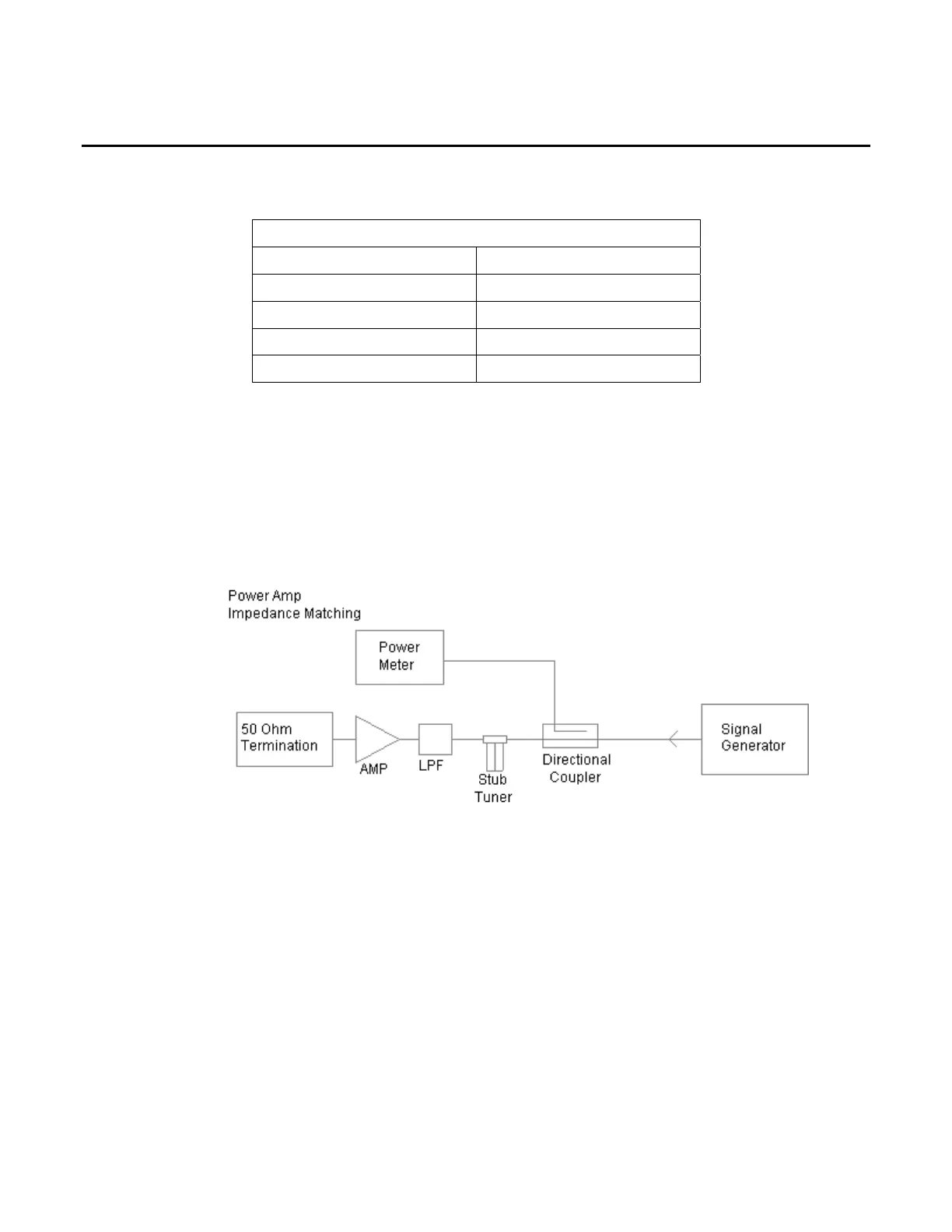
RF COUPLED PORT ATTENUATION
12. Connect test equipment:
13. Set the RF Signal Generator to 500 MHz, CW and 10 dBm.
14. Set the RF Power Meter to 500 MHz, Relative OFF and Offset value to 500 MHz coupled
port attenuation recorded in Step 7.
15. Connect a 50 Ω Termination to the RF Power Amplifier input.
16. Turn RF Power Amplifier to ON, set Gain to maximum and ALC to OFF.
17. Adjust Stub Tuner for lowest RF Power Meter reading <-15 dBm (25 dB return loss).
18. Turn RF Power Amplifier to OFF.