2-46 Subject to Export Control, see Cover Page for details.
E. RF Power Meter Calibration (cont)
49. Press the F5 “Next” Key until the displayed Index is 0.
NOTE
Index: numbers increment by one and the Target dBm: indicates the cal point
power.
50. Using the Arrow Keys ( ), move the cursor to the Table dBm Value.
51. Turn the RF Power Amplifier to ON.
52. Set the RF Signal Generator to RF ON.
53. Adjust the RF Signal Generator level until the power into the T/R Connector, displayed on
the RF Power Meter, is equal to the Target dBm value (± 0.3 dB).
54. Press the F1 “Edit” Key to highlight the field. Change the Table dBm value to match the
RF Power Meter value. Press the F1 “Done” Key to store the setting.
55. Press the F5 “Next” Key to move to the next cal point.
NOTE
Index: numbers increment by one and the Target dBm indicates the cal point
power.
56. Repeat Steps 53 to 55 until the Index returns to 0.
57. Set the RF Signal Generator to RF OFF.
58. Set the RF Amplifier to OFF.
59. Press the F3 “Save” Key.
60. Cycle power on the Test Set.
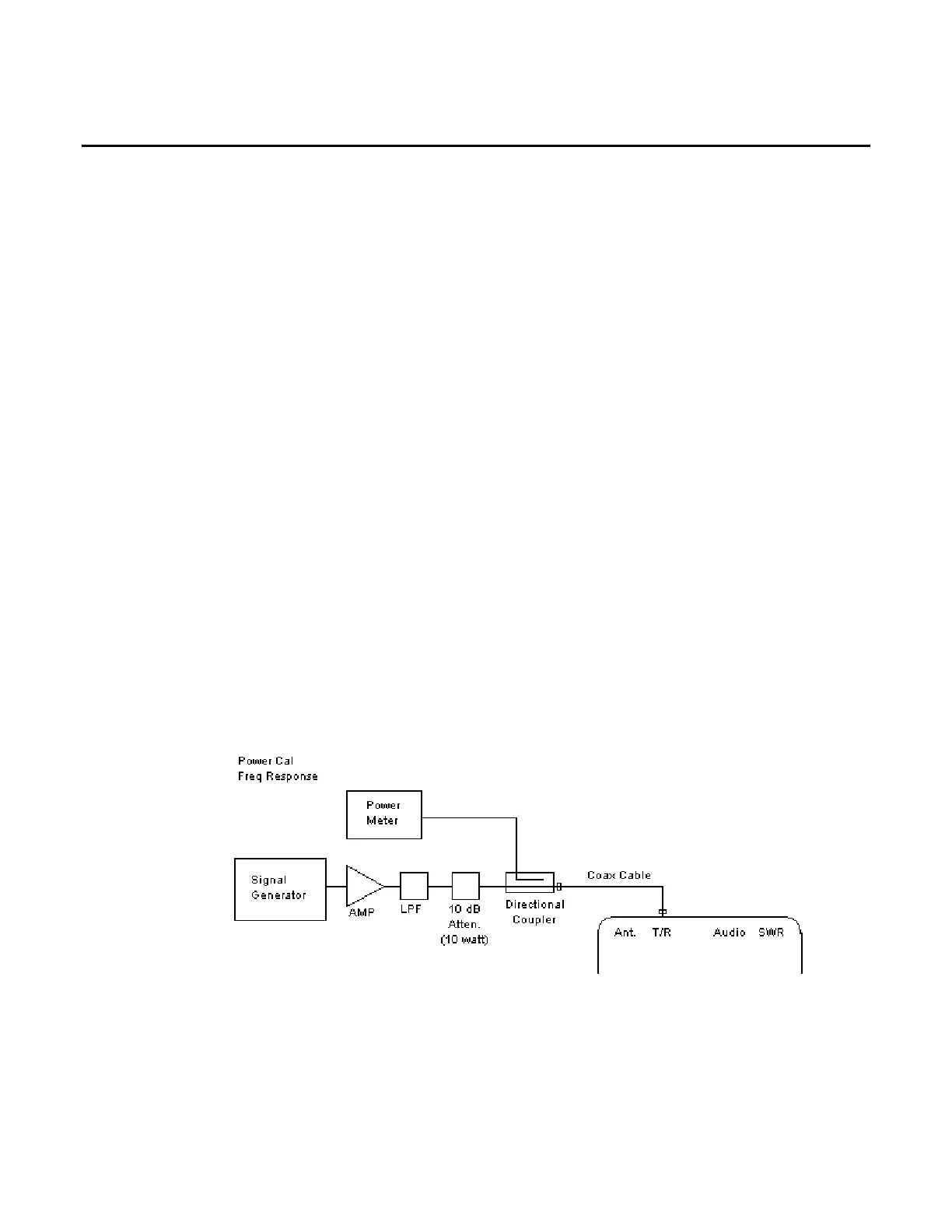
FREQUENCY RESPONSE POWER CAL
61. Connect test equipment (using 100 MHz Low-Pass Filter):